
Plug-in card fixing structure

A fixed structure, plug-in card technology, applied in the direction of electrical components, coupling devices, circuits, etc.

Inactive Publication Date: 2009-08-26
COMPAL ELECTRONICS INC
View PDF0 Cites 4 Cited by
  • Summary
  • Abstract
  • Description
  • Claims
  • Application Information

AI Technical Summary

Problems solved by technology

All the above inconveniences make manufacturers need to improve the card fixing structure

Method used


Image

  • Plug-in card fixing structure
  • Plug-in card fixing structure
  • Plug-in card fixing structure

Examples


Embodiment Construction

[0025] Please refer to Figure 4 , Figure 5 , which shows a card fixing structure according to a preferred embodiment of the present invention. The card fixing structure 200 includes a substrate 202 (such as a printed circuit board), a card edge connector 204 and a supporting frame 206 . Figure 4 , Figure 5 Two fixing methods of the support frame 206 are shown respectively, so that the screw holes 206c on the support frame 206 are different from the card edge connector 204 (directions of the two are opposite), thereby fixing cards of different lengths.

[0026] The supporting frame 206 is composed of a bottom plate 206a, two side plates 206b and two fixing parts (such as screw holes 206c). The two side panels 206b extend vertically upward from two sides of the bottom panel 206a and are parallel to each other. The distance between the two side plates 206 b is approximately equal to the connecting edge 204 a of the card edge connector 204 . Two screw holes 206c are respe...


PUM


Abstract

The invention discloses a plug-in card fixing structure, which comprises a substrate, a card edge connector and a support frame, wherein the card edge connector is positioned on the substrate to connect a plug-in card with the card edge connector in the direction approximately parallel to the substrate; the support frame is provided with a bottom board, two lateral plates and two fixing pieces; the bottom board is attached and fixed on the substrate; the two lateral plates extend outwards from two sides of the bottom board; the two fixing pieces are positioned on the top edges of the lateral plates; and the bottom board is selectively fixed on one of a plurality of positions of the substrate to make the two fixing pieces to fix one side of the plug-in card, which is not connected with the card edge connector. The fixing structure can reduce the bore number of the substrate, relatively increase the wiring area of the circuit boards and improve the stability of the plug-in card.

Description

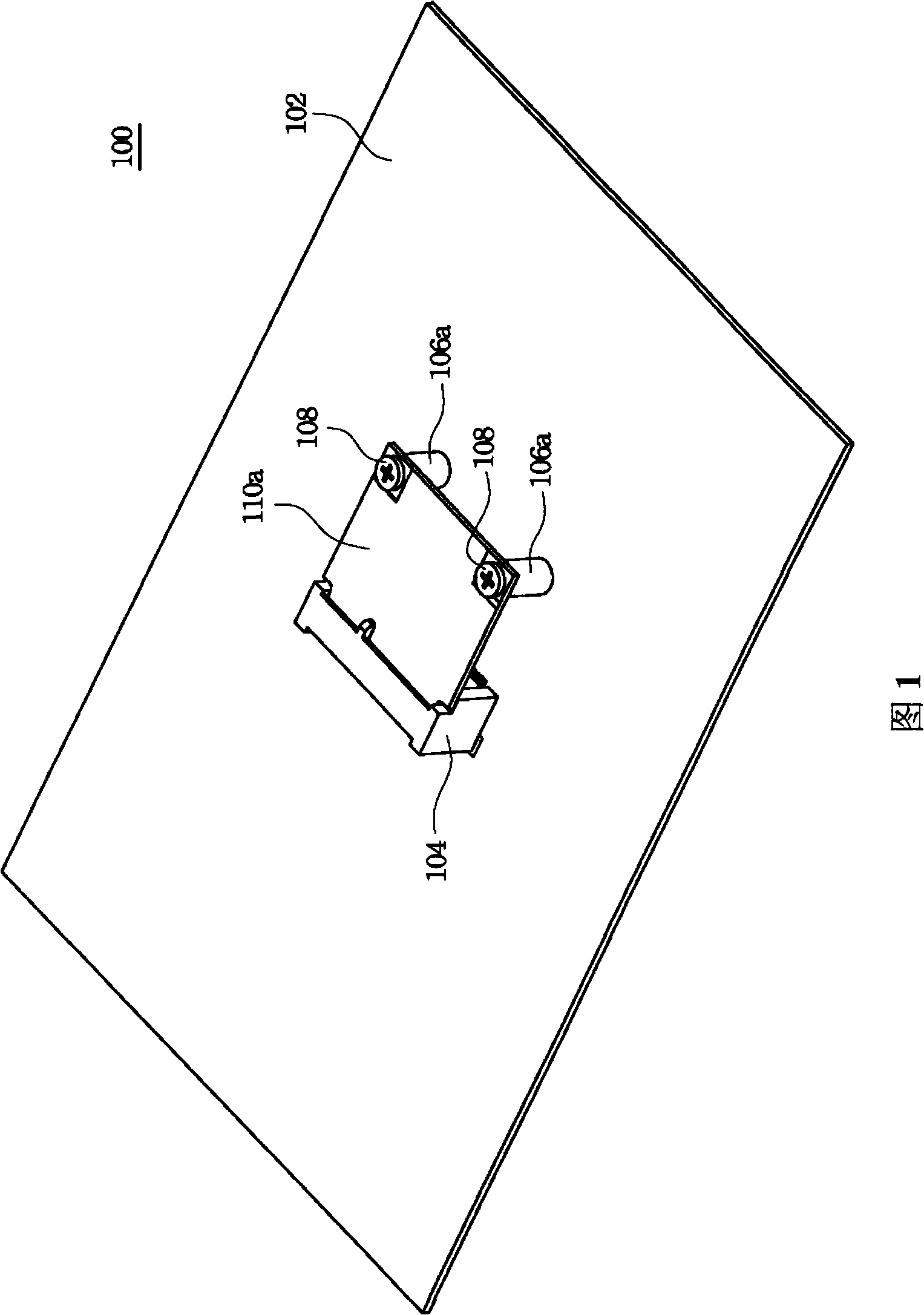
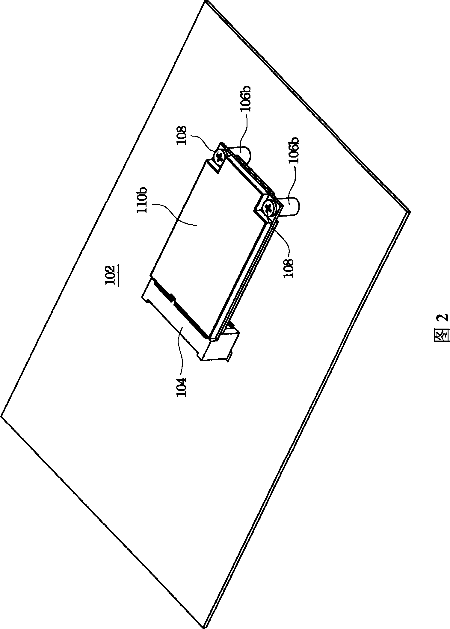
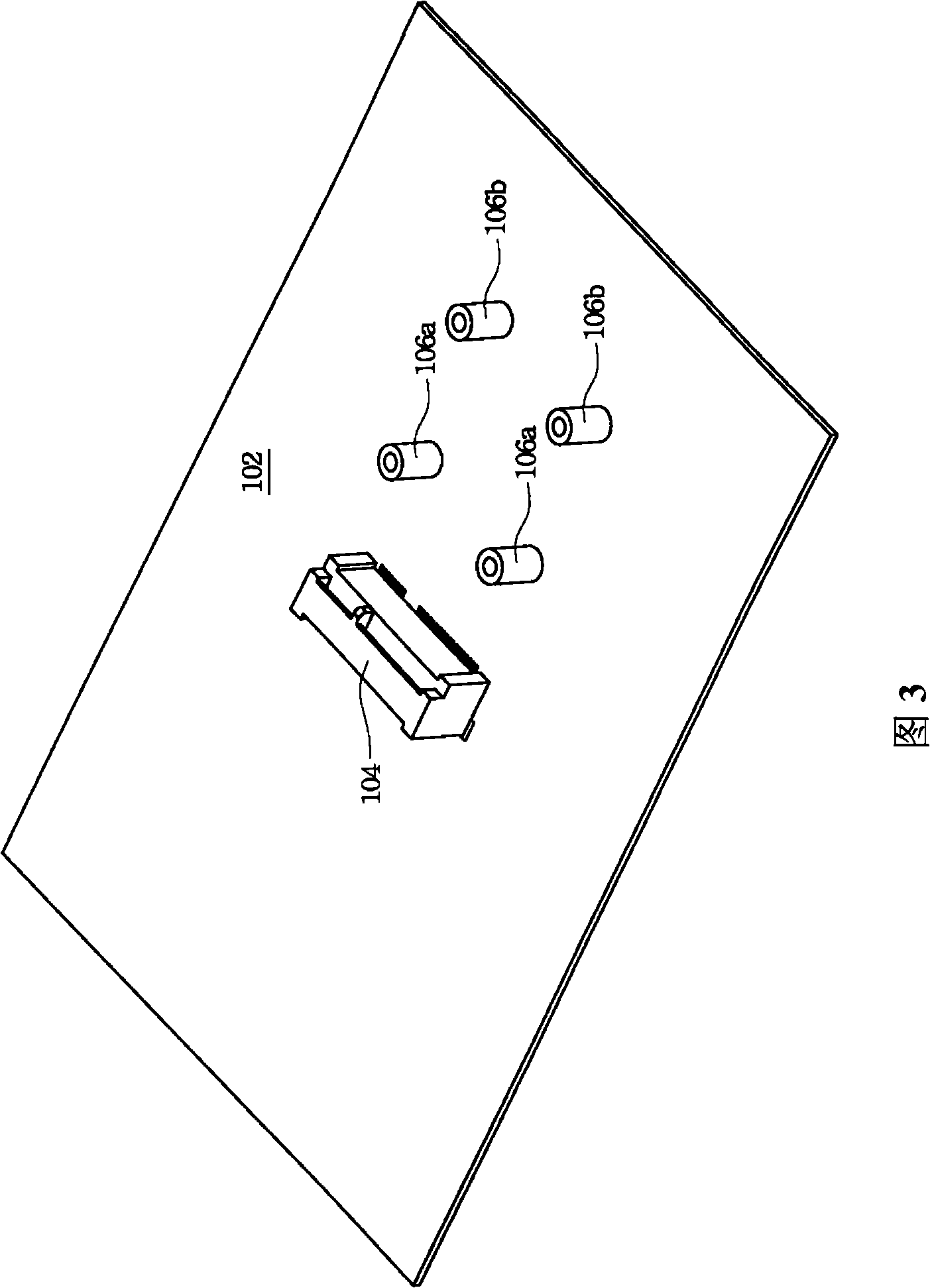
technical field [0001] The invention relates to a connection and fixing structure of a circuit board, and in particular to a card fixing structure. Background technique [0002] Please refer to figure 1 , figure 2 , which respectively represent the known fixing structures for fixing the long and short cards. As consumers have higher and higher requirements for product functions and miniaturization, the development trend of electronic products is to combine miniaturization and multi-function. To this end, manufacturers have developed modular designs to integrate the required circuit layout and electronic components into electronic cards or printed circuit boards to save space and facilitate installation. by figure 1 , figure 2 For example, the short card 110a and the long card 110b are modular electronic cards. The card edge connectors 104 to which the short card 110a and the long card 110b are connected are the same. However, because the lengths of the short card 11...

Claims


Application Information

Patent Timeline
IPC IPC(8): H01R13/639H01R12/18H01R12/73
Inventor 江荣盛
Owner COMPAL ELECTRONICS INC
Learn More