Eureka AIR delivers breakthrough ideas for toughest innovation challenges, trusted by R&D personnel around the world.

Data transmission method based on data transmission system of monitoring terminal

A technology of data transmission system and data transmission method, which is applied in signal transmission system, non-electrical signal transmission system, closed-circuit television system, etc., and can solve the problems of unsuitable low-speed communication applications, poor equipment stability, and increased product costs, etc. problems, to achieve the effects of strong practicability, strong real-time performance, and low system cost

Inactive Publication Date: 2011-06-22
TIANJIN TIANDY DIGITAL TECH
View PDF0 Cites 0 Cited by
  • Summary
  • Abstract
  • Description
  • Claims
  • Application Information

AI Technical Summary

Problems solved by technology

[0004] On the one hand, although the existing technology can support a data rate of up to 50M, there is a huge disadvantage in terms of design cost, and it is not suitable for low-speed communication applications. This will undoubtedly increase the cost of the product, and it is difficult to use point-to-point optical transmission in the intense monitoring industry. Occupy an advantage in market competition; on the other hand, the transmission equipment of the prior art is limited by the processor in use and is often subject to failures such as crashes, and the stability of the equipment is not good

Method used


Image

  • Data transmission method based on data transmission system of monitoring terminal
  • Data transmission method based on data transmission system of monitoring terminal
  • Data transmission method based on data transmission system of monitoring terminal

Examples


Embodiment Construction

[0034] The present invention will be described in detail below with reference to the drawings and examples.

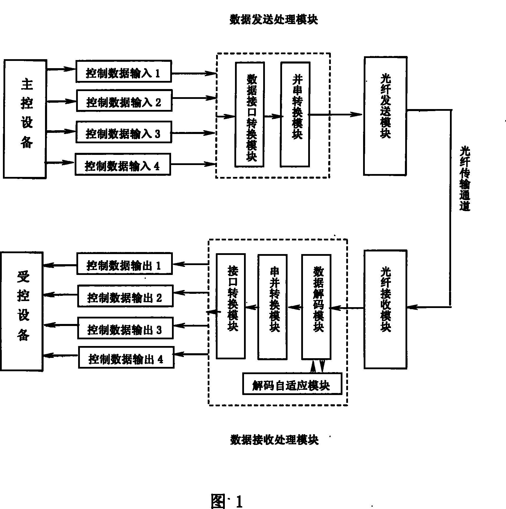
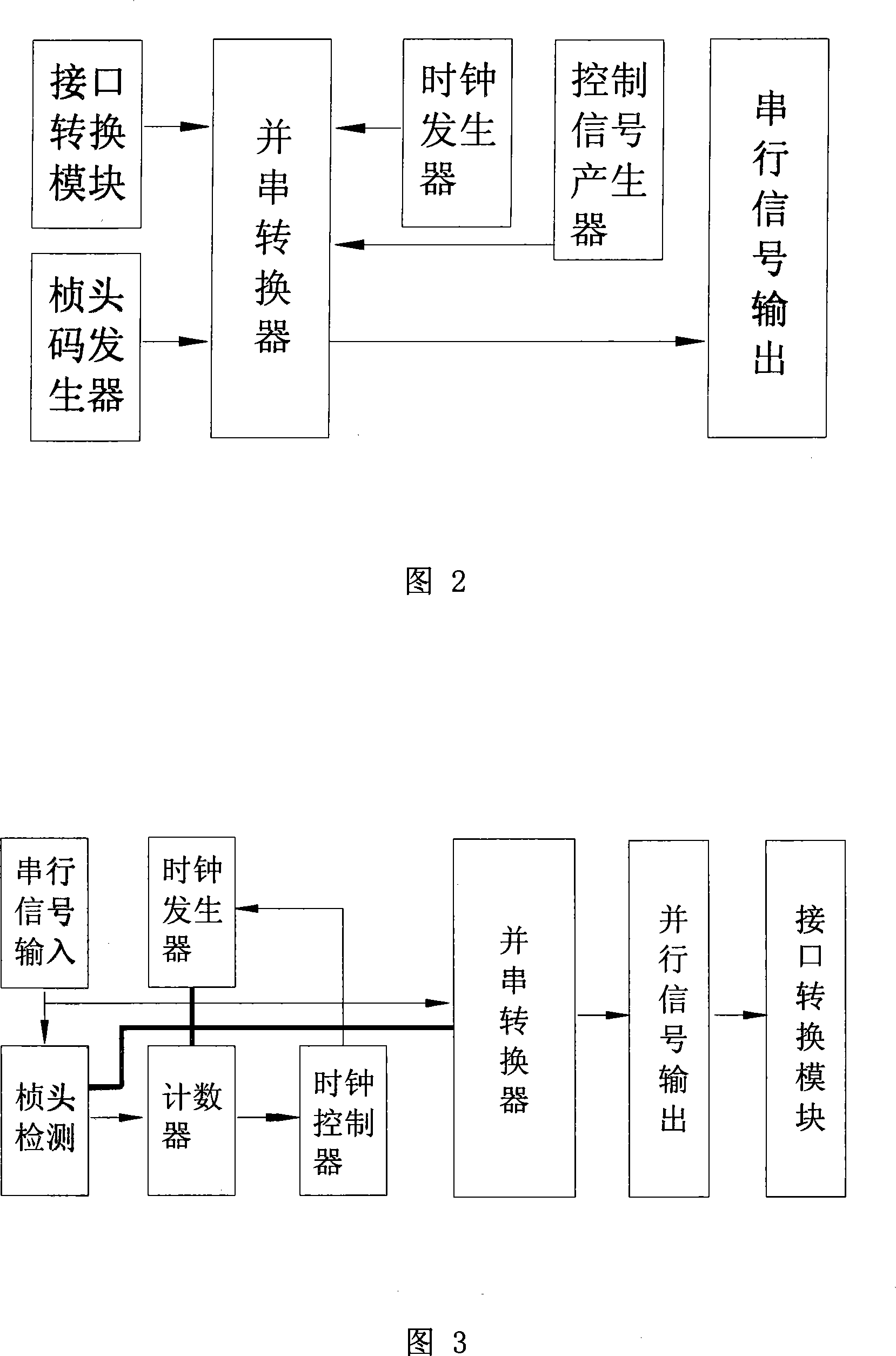
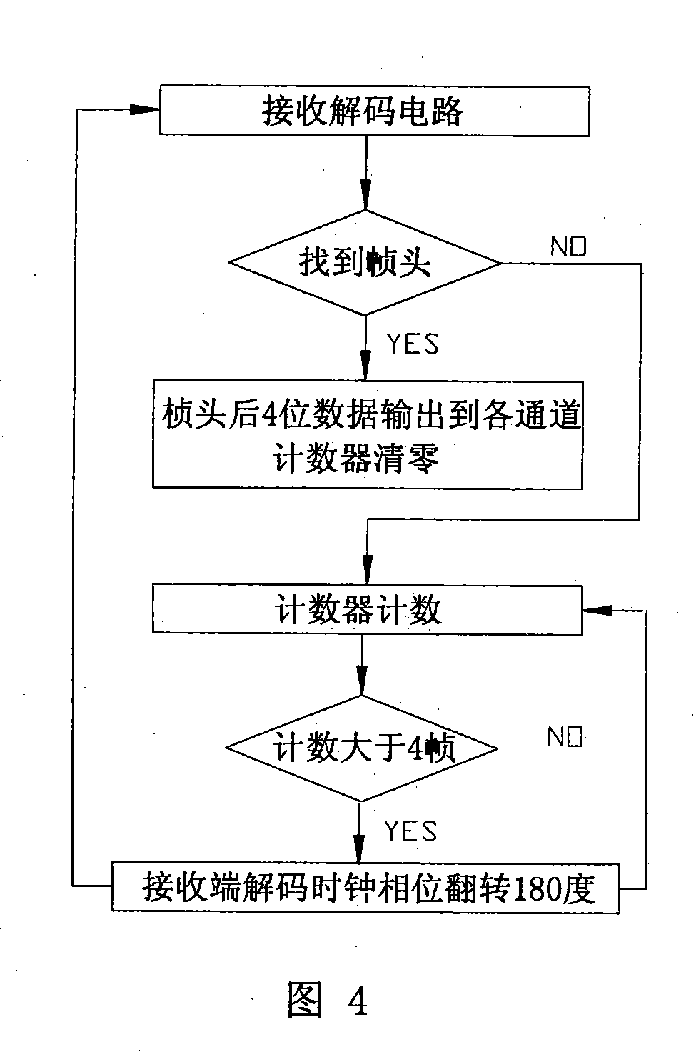
[0035] figure 1 is a schematic diagram of the monitoring terminal data transmission system of the present invention; figure 2 It is a structural data block diagram of the data transmission processing module in the monitoring terminal data transmission system of the present invention; image 3 It is a structural data block diagram of the data receiving and processing module in the monitoring terminal data transmission system of the present invention; Figure 4 It is the workflow diagram of the decoding adaptive module.

[0036] Such as figure 1 As shown, the monitoring terminal control data transmission system of the present invention includes: a data transmission processing module for receiving the control data of the main control device, an optical fiber transmission module, an optical fiber transmission channel, an optical fiber receiving module, and an optical f...


PUM


Abstract

The invention provides a data transmission method based on a monitoring terminal data transmission system. The monitoring terminal data transmission system comprises a data sending and processing module consisting of a data interface conversion module and a parallel-to-serial conversion module; an optical fiber sending module, an optical fiber transmission channel, an optical fiber receiving module and a data receiving and processing module which consists of a data decoding module, a serial-to-parallel conversion module, a decoding self-adaptive module and an interface conversion module; and a plurality of receiving and processing module which consists of a data decoding module, a serial-to-parallel conversion module, a decoding self-adaptive module and an interface conversion module; and a plurality of channels of control data of a controlling device are transmitted to a controlled device side trough the various modules. The invention adopts a self-designed data re-use protocol and a decoding protocol, the decoding self-adaptive module is realized by a programmable logic device CPLD, the system cost is low and the practicability is strong; the invention can be adjusted arbitrarily according to needs without the increase of design cost; the signal transmission has strong real-time property; and the realization thereof is based on the programmable logic device, thereby realizing the pure logicoperation, having no crash risk of CPU and other systems and having high system stability.

Description

technical field [0001] The invention relates to the technical field of monitoring terminals, in particular to a data transmission method based on a monitoring terminal data transmission system with high product integration, low production cost, stable operation and good real-time performance. Background technique [0002] At present, with the development of the monitoring industry, the current monitoring is not just simple system construction such as video transmission and PTZ control of the front-end monitoring terminal, but the entire safe city system that includes applications such as intelligent transportation and public security networking. Point-to-point optical fiber transmission equipment with long-distance transmission capabilities has become an important part of the monitoring system. At this time, the control data that needs to be transmitted includes not only controlling the PTZ signal, but also controlling the on-site vehicle detector, red light detector signal, ...

Claims


Application Information

Patent Timeline
Patent Type & Authority Patents(China)
IPC IPC(8): G08C23/06H04N7/18
Inventor 戴林薛超
Owner TIANJIN TIANDY DIGITAL TECH
Why Eureka
Eureka Blog
Learn More