Power polar protective circuit

A technology of polarity protection and power supply, which is applied in the direction of emergency protection circuit devices and electrical components, etc., and can solve problems such as major accidents, electronic equipment not working normally, equipment burning, etc.

Inactive Publication Date: 2009-09-02
HONG FU JIN PRECISION IND (SHENZHEN) CO LTD +1
View PDF0 Cites 1 Cited by
  • Summary
  • Abstract
  • Description
  • Claims
  • Application Information

AI Technical Summary

Problems solved by technology

[0002] When electronic equipment is powered by an external DC power supply, the polarity of its input must be the same as that of the output terminal of the external DC power supply in order to be able to work effectively and safely. When the operator connects the electronic equipment to the external power supply, sometimes the ...

Method used


Image

  • Power polar protective circuit

Examples


Embodiment Construction

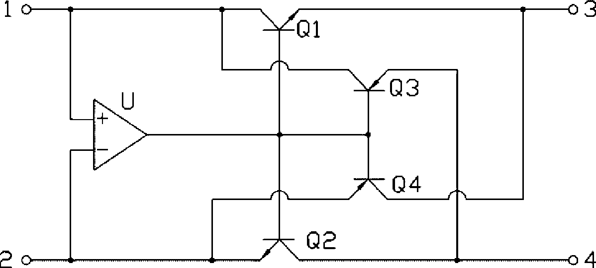
[0008] Please refer to figure 1 , the power supply polarity protection circuit of the present invention is installed between an electronic equipment power supply input terminal and a DC power supply (not shown), and its preferred embodiment includes two input terminals 1 and 2, a comparison amplifier U, four as electronic The transistors Q1, Q2, Q3 and Q4 of the switch and the positive and negative output terminals 3 and 4, the transistors Q1 and Q2 are NPN transistors, and the transistors Q3 and Q4 are PNP transistors.

[0009] The input terminals 1 and 2 are used to connect the positive and negative poles of the DC power supply, the positive and negative input terminals of the comparative amplifier U are respectively connected to the input terminals 1 and 2, and the triodes Q1, Q2, Q3 The bases of Q4 and Q4 are all connected to the output terminal of the comparative amplifier U, the collector of the triode Q1 is connected to the input terminal 1, the emitter is connected to ...


PUM


Abstract

The invention relates to a power polar protective circuit, which comprises a first input end, a second input end, a comparison amplifier, a first electronic switch, a second electronic switch, a third electronic switch, a fourth electronic switch, a positive output end and a negative output end. A positive input end and a reverse input end of the comparison amplifier are connected to the first input end and the second input end respectively; when the first input end and the second input end are connected with a positive electrode and a negative electrode of a DC power supply respectively, the first electronic switch and the second electronic switch are conducted, and the positive output end and the negative output end are communicated with the first input end and the second input end respectively; and when the first input end and the second input end are connected with the negative electrode and the positive electrode of the DC power supply respectively, the positive output end and the negative output end are communicated with the second input end and the first input end through the fourth electronic switch and the third electronic switch, so that a correct polar is output. The power polar protective circuit has a simple structure.

Description

technical field [0001] The invention relates to a power supply polarity protection circuit. Background technique [0002] When electronic equipment is powered by an external DC power supply, the polarity of its input must be the same as that of the output terminal of the external DC power supply in order to be able to work effectively and safely. When the operator connects the electronic equipment to the external power supply, sometimes the The positive and negative power input terminals of the electronic equipment and the positive and negative output terminals of the external power supply are reversely connected, which may cause the electronic equipment to not work normally, or cause the equipment to burn out, or even a major accident, resulting in irreparable losses. Contents of the invention [0003] In view of the above, it is necessary to provide a power supply polarity protection circuit to protect electronic equipment from being damaged when the polarity of the exte...

Claims


Application Information

Patent Timeline
IPC IPC(8): H02H11/00
Inventor 赵泉亮龙俊成
Owner HONG FU JIN PRECISION IND (SHENZHEN) CO LTD
Why Eureka
Try Eureka