
Friction welding methods and friction welding apparatuses

A friction welding and control device technology, applied in welding equipment, non-electric welding equipment, metal processing equipment, etc., to achieve the effect of reducing indentation and reducing burrs

Inactive Publication Date: 2009-09-09
TOYOTA IND CORP +1
View PDF3 Cites 8 Cited by
  • Summary
  • Abstract
  • Description
  • Claims
  • Application Information

AI Technical Summary

Problems solved by technology

However, the above-mentioned method is only a method corresponding to aluminum alloys, not a method that can correspond to general friction welding

Method used

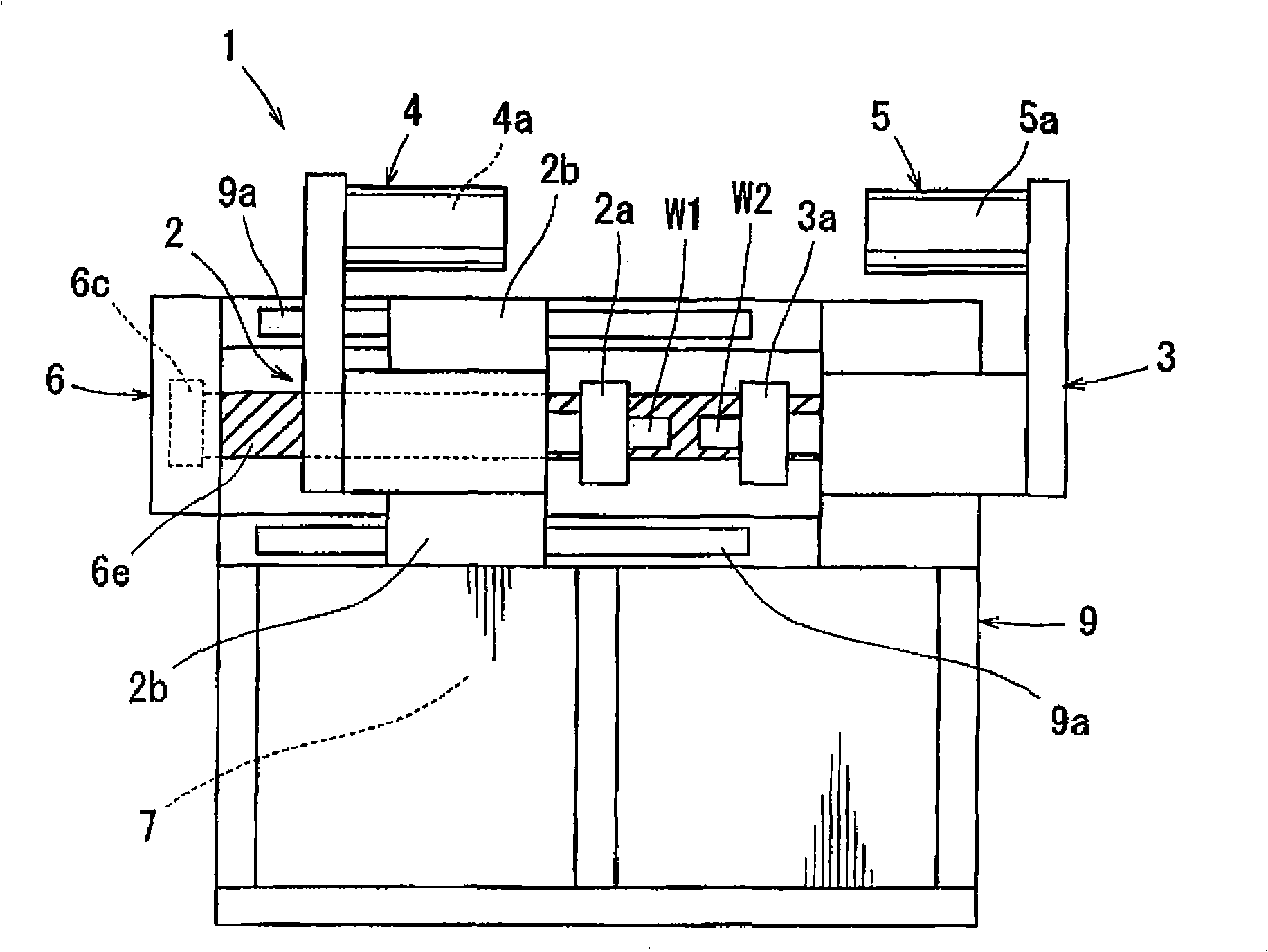
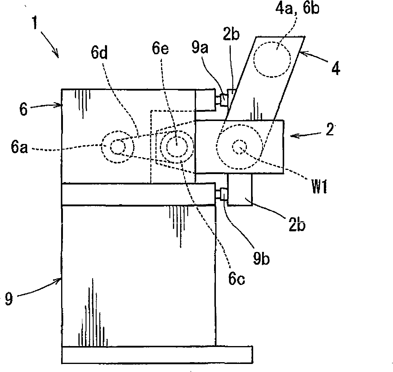
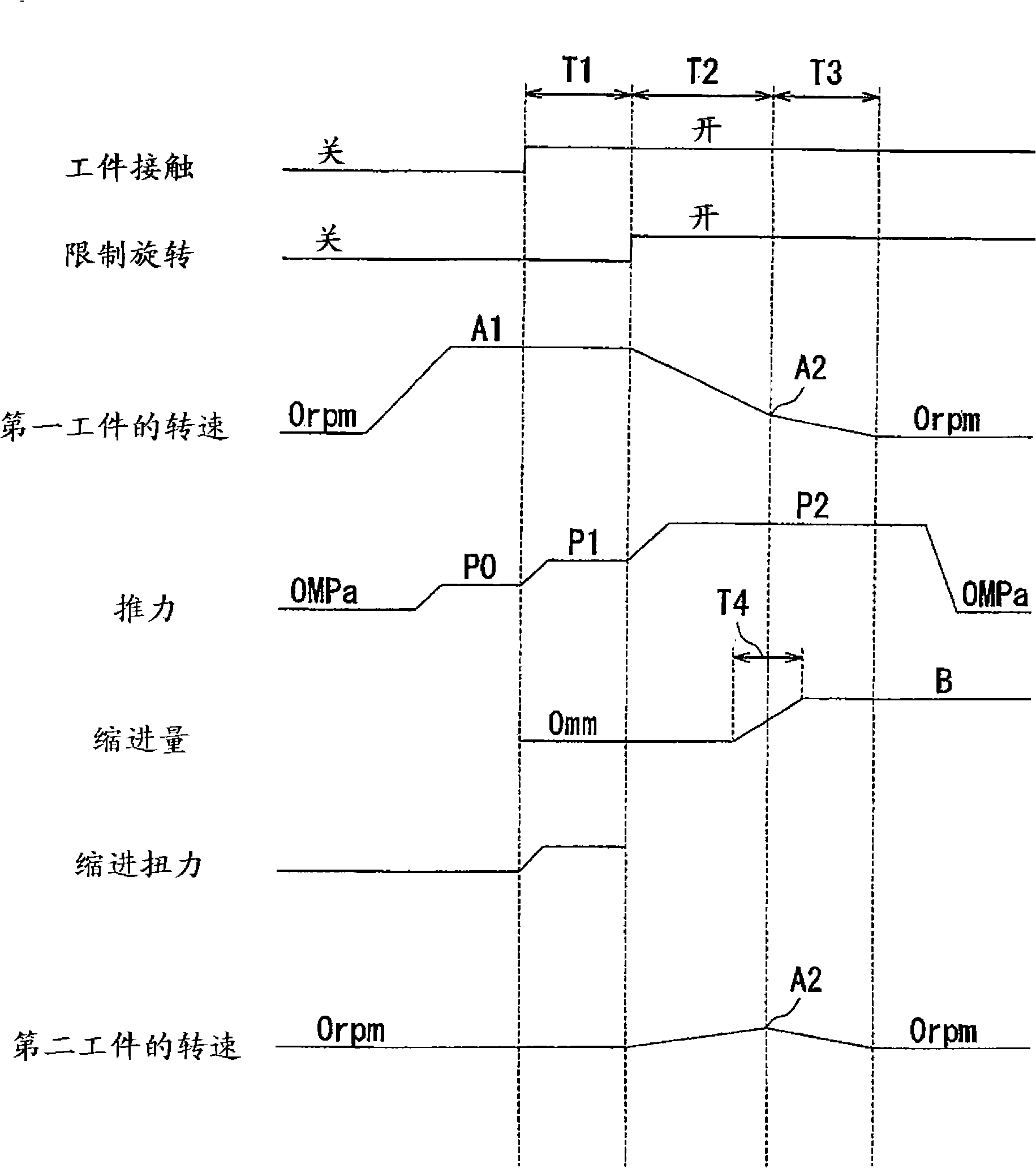

Image

  • Friction welding methods and friction welding apparatuses
  • Friction welding methods and friction welding apparatuses
  • Friction welding methods and friction welding apparatuses

Examples


Embodiment Construction

[0014] Each additional feature and teaching content disclosed in the context can be used alone or in combination with other additional features and teaching content to provide an improved friction welding method and friction welding device. Now, typical examples of the present invention will be described in detail with reference to the accompanying drawings, which utilize some of these additional features and teaching contents both individually and in combination with each other. This detailed description is only intended to teach those skilled in the art further details in order to practice the preferred aspects of this teaching, and is not intended to limit the scope of the present invention. Only the claims define the scope of the invention. Therefore, the combination of features and steps disclosed in the following detailed description may not necessarily be necessary to practice the present invention in the broadest sense, but the purpose of teaching is only to specifically i...


PUM


Abstract

One aspect of the present invention can include a friction welding method having a friction step for generating a friction heat by pressing the pair of works (W1,W2) while relatively rotating the pair of works (W1,W2), and an upset step started before generating an approach margin at the pair of works (W1,W2) at the friction step, restricting rotation of the pair of works (W1,W2) relative to each other and applying an upset pressure between the pair of works (W1,W2).

Description

[0001] This application claims the priority of Japanese Patent Application Nos. 2008-54581 and 2009-7790, the contents of which are incorporated herein by reference. Technical field [0002] The invention relates to a friction welding method and a friction welding device. The friction welding device is used for friction welding a pair of workpieces by pressing the pair of workpieces while rotating the pair of workpieces relative to each other. Background technique [0003] In the background art, various friction welding methods are known, for example, the known LHI method (refer to Japanese Laid-Open Patent Publication No. 2003-62676) and a method suitable for aluminum alloys (refer to Japanese Laid-Open Patent Publication No. H05-96385), etc. . According to the LHI method, frictional heat is generated by making the pair of workpieces abut against each other while rotating the pair of workpieces relative to each other. Further, the relative rotation continues until the friction to...

Claims


Application Information

Patent Timeline
Patent Type & Authority Applications(China)
IPC IPC(8): B23K20/12
CPCB23K20/12B23K20/121B23K20/26
Inventor 川浦广一松林哲也水谷明
Owner TOYOTA IND CORP
Learn More