Shutter type hydraulic self-control gate

A hydraulic automatic control, shutter-type technology, applied in water conservancy projects, marine engineering, coastline protection and other directions, can solve the problems of slow opening and closing speed, high technical level requirements, large opening and closing resistance of lying down doors, etc., to reduce navigation. The effect of water level error, improving navigation efficiency and shortening navigation time

Active Publication Date: 2009-09-09
ZHEJIANG UNIV
View PDF0 Cites 16 Cited by
  • Summary
  • Abstract
  • Description
  • Claims
  • Application Information

AI Technical Summary

Problems solved by technology

In the past, the regulation of tidal resources was carried out in the form of traditional sluice gates. Because this kind of sluice gate cannot adapt to the fluctuation of tides, it needs to be controlled manually, which has brought about difficult control of reservoir sediment, low utilization rate of tidal resources, and manipulation technology. A series of problems such as high level requirements, therefore, there is an urgent need for a new type of self-controlled gate with hydraulic adaptive capacity
[0003] In the navigation of the ship lift, the recumbent door is often used as the working gate of the ship-bearing compartment. The traditional recumbent door has a large opening and closing resistance and a slow opening and closing speed, which affects the navigation speed of the ship lift and affects the ship's bearing capacity. Therefore, in the field of navigation, a new type of working gate with certain hydraulic adaptive capacity is also required.

Method used


Image

  • Shutter type hydraulic self-control gate
  • Shutter type hydraulic self-control gate
  • Shutter type hydraulic self-control gate

Examples


Embodiment Construction

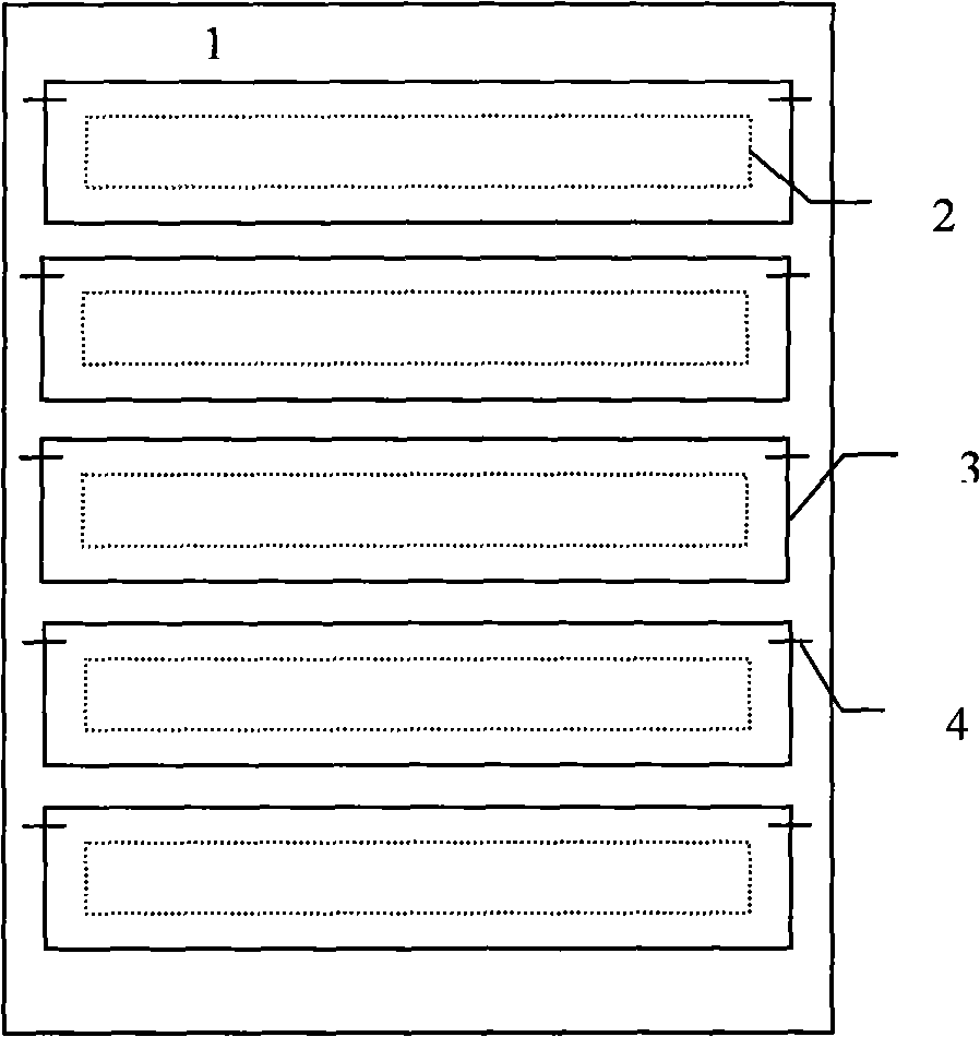
[0015] Such as figure 1 , 2 As shown, the louver type hydraulic automatic control gate includes a gate frame 1, a window mullion 2, a small door leaf 3 and a small door shaft 4; a plurality of window mullions 2 are arranged in the gate frame 1, and a small door shaft 4 is arranged on the top of the window mullion 2, Hang the small door leaf 3 on the small door shaft 4.

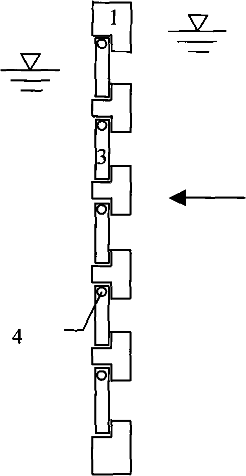
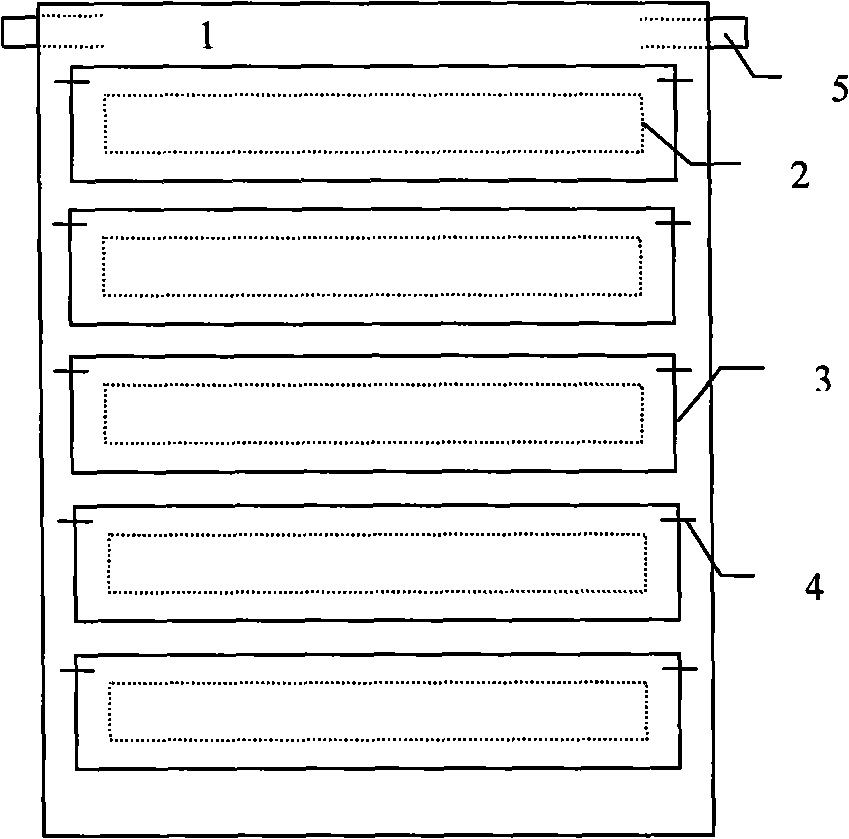
[0016] Such as image 3 As shown, the louver type hydraulic automatic control gate includes a gate frame 1, a window mullion 2, a small door leaf 3 and a small door shaft 4; a plurality of window mullions 2 are arranged in the gate frame 1, and a small door shaft 4 is arranged on the top of the window mullion 2, A small door leaf 3 is hung on the small door shaft 4, and a large door shaft 5 is arranged on the top of the gate frame 1 to form a jacking type louver hydraulic automatic control gate.

[0017] Such as Figure 4 As shown, the louver type hydraulic automatic control gate includes a gate frame 1, a...


PUM


Abstract

The invention discloses a shutter type hydraulic self-control gate. The shutter type hydraulic self-control gate comprises a gate frame, window lattices, small door leaves and small door spindles, wherein, a plurality of window lattices are arranged in the gate frame; the small door spindles are arranged at the top part of the window lattices; the small door leaves are suspended on the small door spindles; a large door spindle is arranged at the top part of the gate frame to form a top spindle shutter type hydraulic self-control gate; and a large door spindle is arranged at the bottom part of the gate frame to form a bottom spindle shutter type hydraulic self-control gate. The top spindle type and fixed type shutter type hydraulic self-control gate can efficiently utilize tidal power resources in riverine and coastal areas and effectively control reservoir deposits of tidal power station, and provides safe energy and water insurance for the development of riverine and coastal areas. The bottom shaft type shutter hydraulic self-control gate can be used as a navigation gate of a ship elevator, reduce the open and close resistance of a flap gate and the error of water level of navigation, shorten navigation time, and comprehensively improve the navigation efficiency of ship elevators. Compared with the traditional gate, the shutter type hydraulic self-control gate has good work state and the passing water current is uniform.

Description

technical field [0001] The invention belongs to the field of water conservancy engineering and marine engineering facilities, and in particular relates to a louver type hydraulic automatic control gate. Background technique [0002] There are abundant tidal resources in the coastal areas along the river. These tidal resources contain huge energy and high-quality water bodies. Tidal energy can be used to generate electricity, change the local energy structure, and alleviate the energy crisis in coastal areas along the river; Clear water, improve the local water environment, improve local disaster prevention and mitigation capabilities, and solve the contradiction of water quality and water shortage in coastal areas along the river, thereby improving local water supply security. In the past, the regulation of tidal resources was carried out in the form of traditional sluice gates. Because this kind of sluice gate cannot adapt to the fluctuation of tides, it needs to be control...

Claims


Application Information

Patent Timeline
Patent Type & Authority Applications(China)
IPC IPC(8): E02B7/20E02B7/44
Inventor 顾正华徐锦才殷蕾
Owner ZHEJIANG UNIV
Why Eureka
Try Eureka