
Peak deformation instrument

A deformation and peak technology, applied in the direction of instruments, measuring devices, mechanical devices, etc., to achieve the effects of personal safety protection, convenient operation, and simple structure

Active Publication Date: 2013-06-26
INST OF ENG MECHANICS CHINA EARTHQUAKE ADMINISTRATION
View PDF6 Cites 0 Cited by
  • Summary
  • Abstract
  • Description
  • Claims
  • Application Information

AI Technical Summary

Problems solved by technology

However, the prior art does not provide an instrument that can be installed at the beam-column joints to judge whether the concrete frame structure has suffered serious damage under the action of a strong earthquake or to judge whether the severely damaged structure is affected by aftershocks or excavation disturbances. Whether to continue to tilt

Method used


Image

  • Peak deformation instrument
  • Peak deformation instrument
  • Peak deformation instrument

Examples


specific Embodiment approach 1

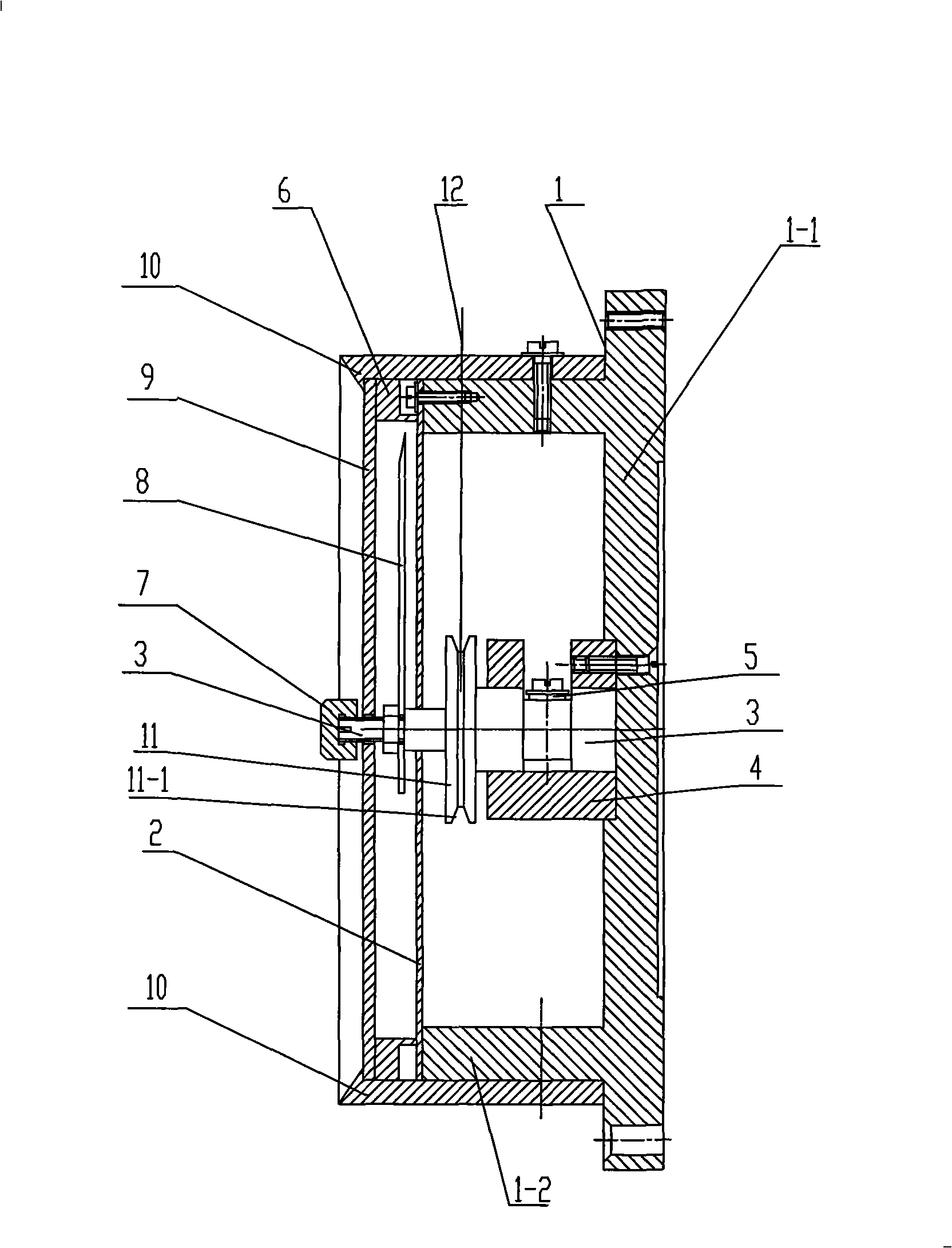
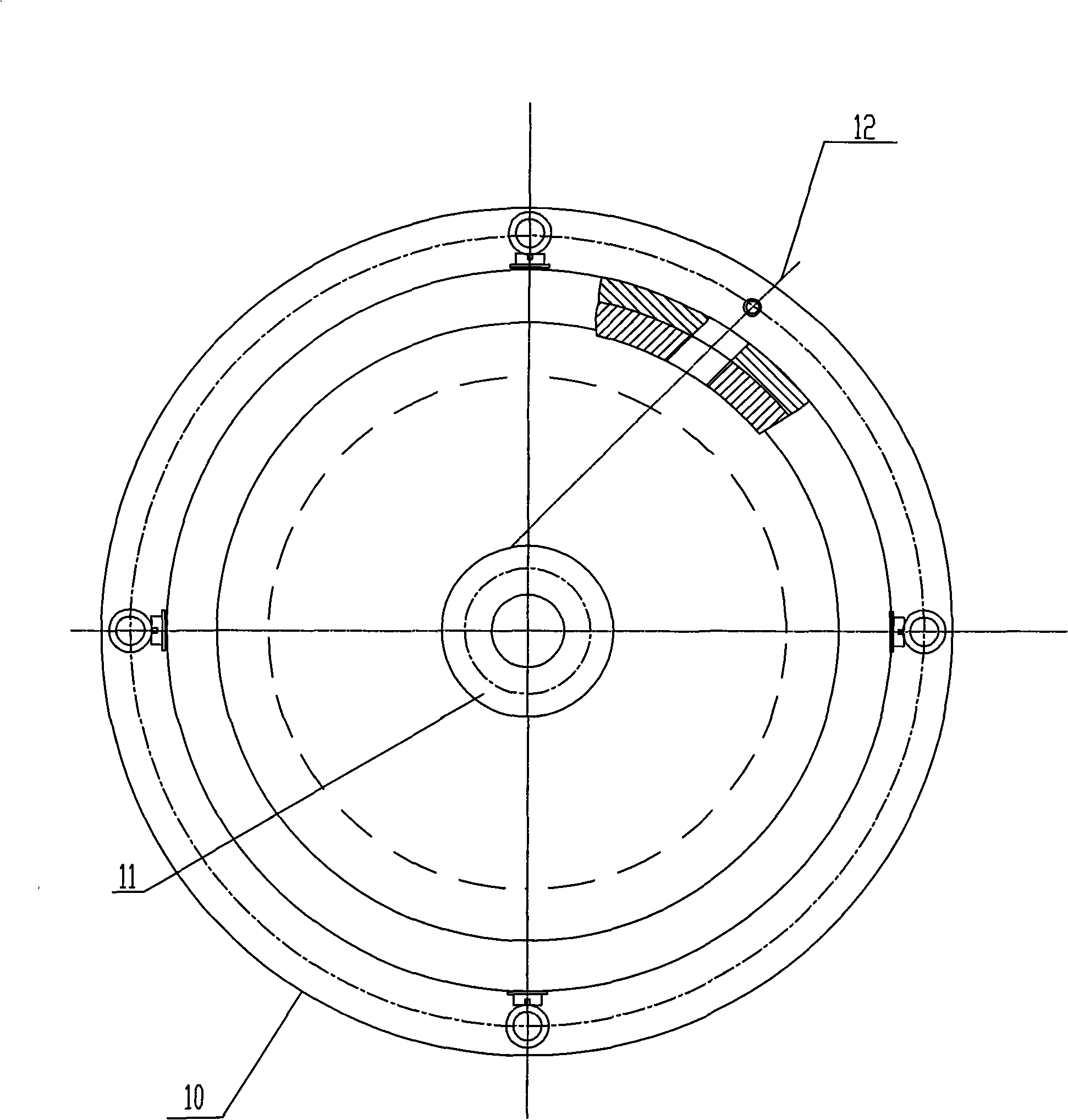
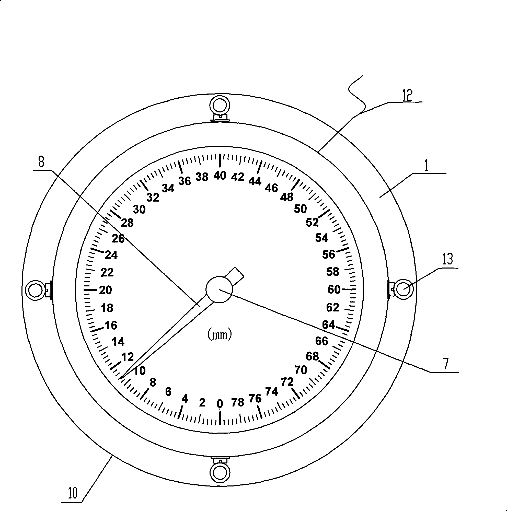
[0007] Specific implementation mode one: as Figure 1 to Figure 5 As shown, the peak strain gauge in this embodiment includes a base 1, a shaft 3, a shaft sleeve 4, a runner 11, a scale disc 2, a pointer 8, an adjusting nut 7 and a measuring rope 12; the base 1 is composed of a base plate 1-1 and cylinder body 1-2, one end surface of cylinder body 1-2 is fixedly connected with substrate 1-1, shaft sleeve 4 is set in base 1 and one end surface of shaft sleeve 4 is fixed with substrate 1-1. Then, one end of the shaft 3 is inserted into the shaft sleeve 4, the runner 11 is located in the base 1 and fixed on the shaft 3, and the scale disk 2 is covered on the other end surface of the cylinder 1-2 and fixedly connected to it. , the other end of the shaft 3 passes through the central hole of the scale disc 2 and is exposed outside, the pointer 8 is located outside the base 1 and is fixed on the shaft 3, the adjusting nut 7 is screwed to the other end of the shaft 3 exposed outside, ...

specific Embodiment approach 2

[0009] Specific implementation mode two: as Figure 1 to Figure 5 As shown, a groove 11-1 is formed on the side wall of the runner 11 in this embodiment. A groove 11 - 1 is formed on the side wall of the running wheel 11 to facilitate the winding of the measuring rope 12 . Other components and connections are the same as those in the first embodiment.

specific Embodiment approach 3

[0010] Specific implementation mode three: as Figure 1 to Figure 5 As shown, in this embodiment, four installation and fixing holes 13 are evenly distributed on the peripheral edge of the substrate 1 - 1 . Other compositions and connections are the same as those in Embodiment 1 or 2.


PUM


Abstract

The invention relates to a peak deformation instrument. The invention is used for judging whether a concrete frame structure is severely damaged under the action of a violent earthquake or judging whether a severely-damaged structure continues inclining under the impact of aftershock or digging interference. An axle sleeve is provided within a base and one end face of the axle sleeve is fixedly connected with a basal plate, one end of an axis is inserted within the axle sleeve, a rotating wheel is located within the base and is fixedly mounted in the middle of the axis, a dial disc is covered on the other end face of a cylinder body and is fixedly connected with the cylinder body, the other end of the axis stretches out of the centre of the dial disc, a pointer is located on the outside of the base and is fixedly mounted on the axis, an adjusting nut is in threaded connection with the other end of the axis, on end of a measuring rope is fixedly connected on the sidewall of the rotating wheel, and the other end of the measuring rope stretches out of the base to be exposed outside. The invention has the advantages of simple structure and convenient operation. By using the invention, emergent interlayer displacement maximum values of construction structure under the action of the earthquake can be obtained in a fixed quantity.

Description

technical field [0001] The invention relates to a peak deformation meter. Background technique [0002] Under the action of strong earthquake, the concrete frame structure will produce relatively large relative deformation between floors, and then plastic hinges will appear at the beam end or column end near the beam-column joint. Some structures have obvious residual deformation (skew) after plastic hinges appear; some columns are not skewed after the earthquake even though plastic hinges appear. Judging whether the structure has suffered serious damage, it is impossible to judge the danger of collapse, which poses a great threat to the post-earthquake search and rescue work. If search and rescue personnel rush into a structure that has been seriously damaged, the structure will collapse under the action of aftershocks or other disturbances, which will inevitably cause new casualties. At this time, if there is some kind of instrument (instrument) that can display the maxi...

Claims


Application Information

Patent Timeline
Patent Type & Authority Patents(China)
IPC IPC(8): G01B5/02
Inventor 郑志华郭迅
Owner INST OF ENG MECHANICS CHINA EARTHQUAKE ADMINISTRATION
Learn More