Centrifugal model retaining wall test device

A technology of test equipment and centrifugal model, applied in the testing of machine/structural components, measuring devices, instruments, etc., can solve the problems of difficult translation, ignoring the influence of gas and oil displacement control, unable to block the static state of the wall, etc. Achieve stable equipment performance, uniform and continuous displacement, and reliable operation.

Inactive Publication Date: 2009-09-09
TSINGHUA UNIV
View PDF0 Cites 16 Cited by
  • Summary
  • Abstract
  • Description
  • Claims
  • Application Information

AI Technical Summary

Problems solved by technology

This equipment uses a cylinder piston to control the movement of the model retaining wall in the horizontal direction, but it cannot control the retaining wall to maintain a static state during the process of increasing centrifugal acceleration, and it cannot control the retaining wall to continuously and uniformly displace to the active side, and it is only suitable for ideal Granular material, cannot be tested on sandy soil
[0004] Through the investigation of existing equipment, it can be seen that most of the existing equipment uses cylinders or oil cylinders as the driving device for the movement of the retaining wall, ignoring the influence of the compressibility of gas and oil on displacement control
The earth pressure centrifugal model test is quite difficult, and the main technical difficulties are as follows: With the increase of centrifugal acceleration, the increase of the lateral pressure of the filling soil behind the wall on the retaining wall will cause the retaining wall to displace to the active side and cannot maintain a static state; It is difficult to move slowly, uniformly and continuously during the movement from the static state to the active state; the motion form of the retaining wall is difficult to control, and it is difficult to maintain translational motion

Method used


Image

  • Centrifugal model retaining wall test device
  • Centrifugal model retaining wall test device
  • Centrifugal model retaining wall test device

Examples


Embodiment Construction

[0018] The principle, specific structure and working process of the present invention will be further described below in conjunction with the accompanying drawings.

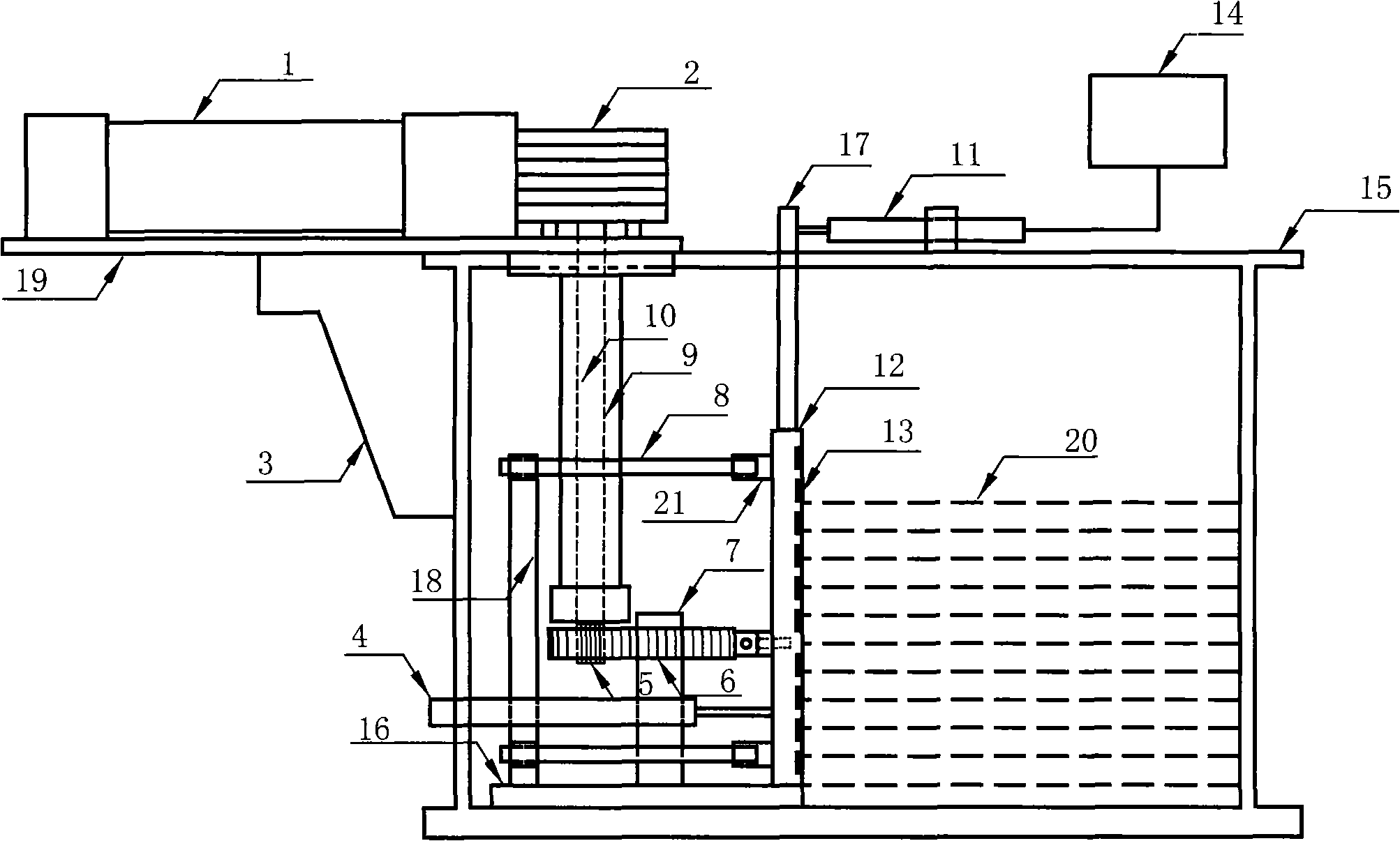
[0019] figure 1 It is a schematic diagram of the principle mechanism of the earth pressure centrifugal model test equipment. The invention mainly consists of four parts: a driving system, a model retaining wall structure, a measuring system and an automatic displacement control system. The following are detailed introductions respectively.

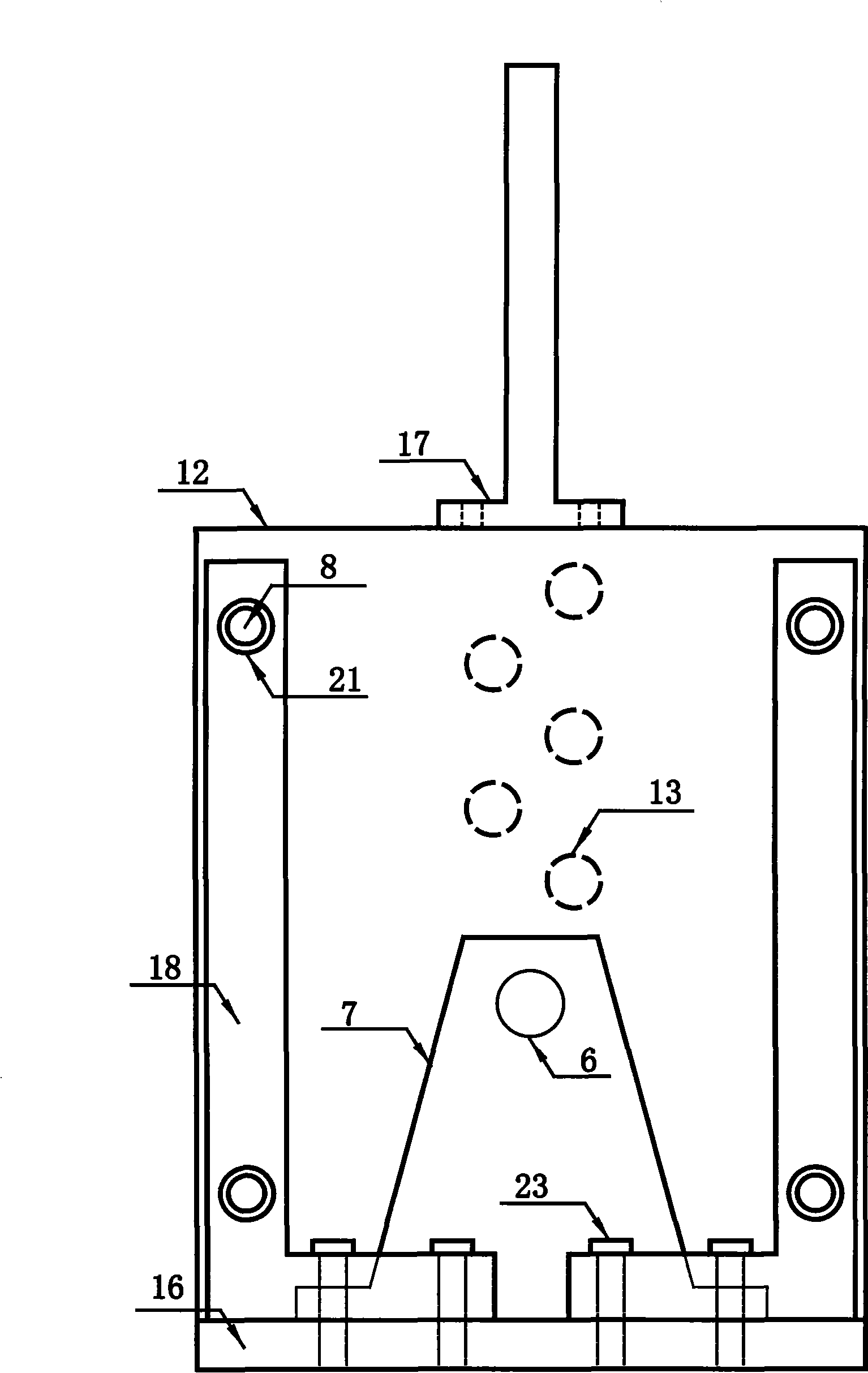
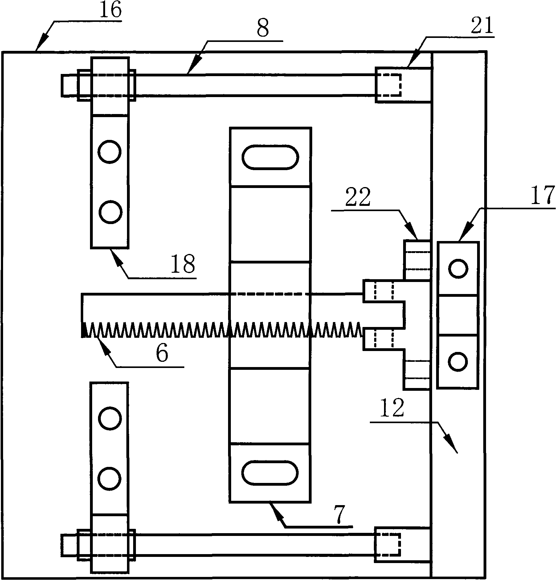
[0020] The drive system includes a motor, a reducer and a transmission mechanism that drives the displacement of the model retaining wall. The transmission mechanism includes a transmission shaft 10, a shaft sleeve 9, a gear 5 and a rack 6. The various components of the drive system are connected and assembled as follows: figure 1 As shown, insert the transmission shaft 10 into the worm gear reducer 2, after adjusting the position of the transmission shaft, fix the transmi...


PUM


Abstract

The invention relates to a centrifugal model retaining wall test device, belonging to the research technical filed of soil pressure centrifugal model test. The device comprises a driving system, a model retaining wall structure, a measurement system and a displacement automatic control system of model retaining wall. The added displacement automatic control system of model retaining wall can guarantee the model retaining wall to be remained at rest during centrifugal acceleration is increased; by adopting an electric motor as the driving system, the displacement of the model retaining wall can be guaranteed to be slow, homogeneous and continuous, and a data acquisition system can be guaranteed to completely record a change process of soil pressure and soil body displacement field during the model retaining wall moves; and an improved structure of the model retaining wall leads the model retaining wall to keep translatory displacement model. The preliminary experimental result shows that the device has stable capability, reliable operation and convenient operation, and is suitable for the research of the rest condition of the rigid retaining wall and the soil pressure of a driving side.

Description

technical field [0001] The invention is a test device specially used for carrying out an earth pressure centrifugal model test on a centrifuge to study the earth pressure problem, and its main technical field is the research technical field of the earth pressure centrifugal model test. Background technique [0002] Soil retaining structures are widely used in civil engineering, water conservancy and hydropower, highway, railway transportation and other engineering constructions, and their purpose is to support the soil to keep it stable. The evaluation of earth pressure is a basic item in the structural design and stability analysis of earth-retaining structures, which is directly related to the safety, reliability and economical rationality of engineering design. The theory and application of earth pressure has become a basic topic in the field of soil mechanics and geotechnical engineering. The geotechnical centrifugal model test reduces the size of the geotechnical struc...

Claims


Application Information

Patent Timeline
Patent Type & Authority Applications(China)
IPC IPC(8): G01M19/00G01M99/00
Inventor 宋飞刘超张建民张嘎郑瑞华
Owner TSINGHUA UNIV
Why Eureka
Try Eureka