Projector
一种投射型影像、显示装置的技术,应用在放映装置、光学、仪器等方向,能够解决跌倒等问题
- Summary
- Abstract
- Description
- Claims
- Application Information
AI Technical Summary
Problems solved by technology
Method used
Image
Examples
Embodiment approach 1
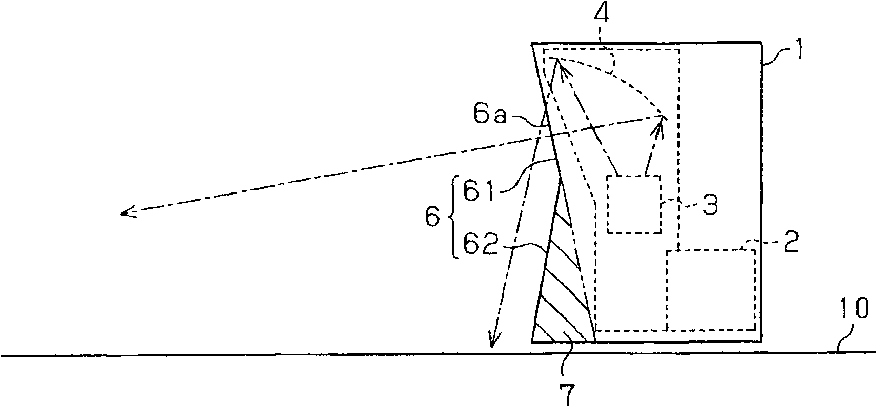
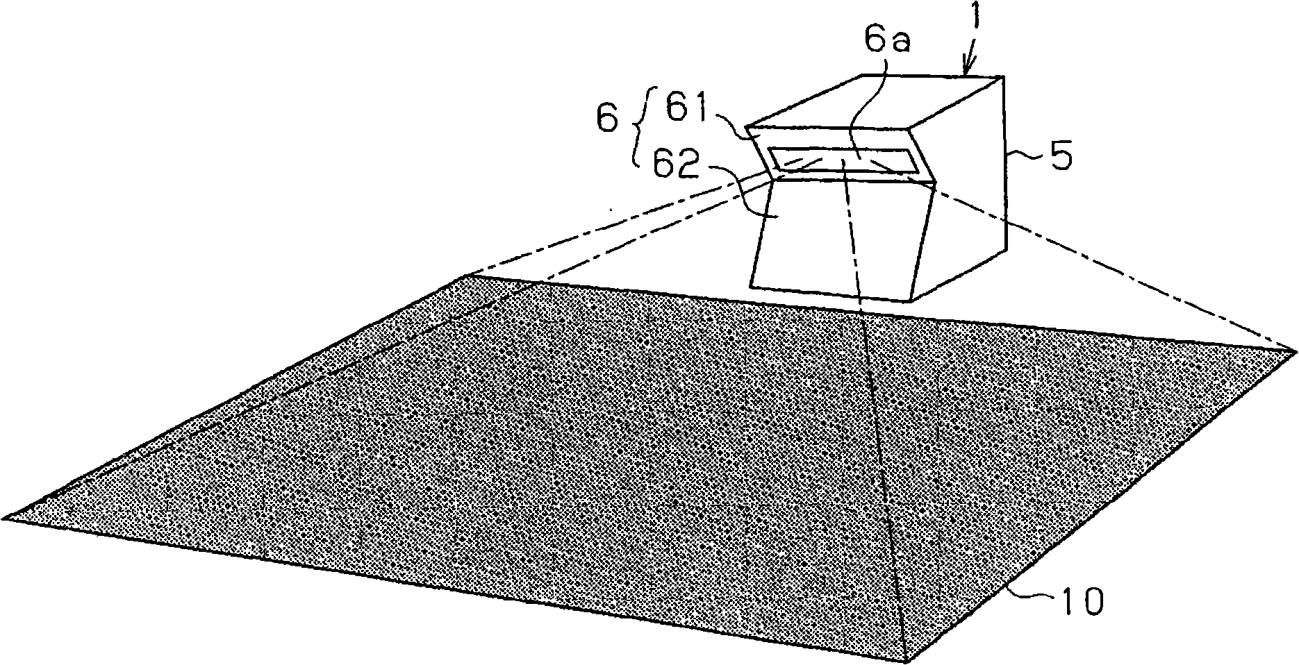
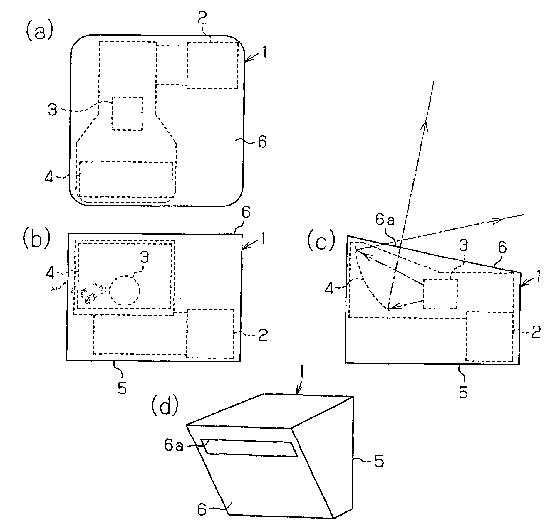
[0027] Next, Embodiment 1 of the present invention will be described in detail with reference to the drawings. The projection type image display device of this embodiment is a liquid crystal projector using a liquid crystal panel as a light modulation element, such as figure 1 As shown, a light source 2 , a projection lens system component 3 , an aspheric mirror 4 , a control circuit component (not shown) and the like are accommodated inside the housing 1 . In this case, if the frame body 1 that does not waste space in the frame body 1 is formed, it becomes image 3 The configuration of the projection type image display device as shown in the reference example is shown. which is, image 3 It is a schematic configuration diagram of a projection type image display device as a reference example, (a) is a plan view in the case of wall projection / floor placement installation, (b) is a reverse projection side (reverse wall side) view in this installation case, ( c) is a side vie...
Embodiment approach 2
[0039] Embodiment 2 such as Figure 6 As shown, the shape of the mirror-side outer surface 6 is changed. That is, in this embodiment, a symmetrical inclined surface is formed only in the vicinity of the boundary line between the first outer surface 61 and the second outer surface 62 of the mirror side outer surface 6 . On the other hand, the other parts of the frame body 1 are formed as approximately rectangular parallelepipeds.
[0040] Since the projection-type video display device according to Embodiment 2 is configured as described above, when the projection-type video display device is configured to be used for floor projection / floor placement, the lower part of the housing 1 is more forward than conventional (projection). side) extended setting state, so the frame body 1 can be prevented from falling. Furthermore, since the frame body 1 is formed in a box shape closer to a cuboid, a more stable appearance can be presented.
Embodiment approach 3
[0042] In Embodiment 3, when the projection type image display device is configured as a floor projection / floor installation and used, instead of occupying the space below the aspheric mirror 4 as in the case of Embodiment 1 or Embodiment 2, form box 1, and as Figure 7 As shown, the pedestal 8 can be detachably mounted on the bottom.
[0043] Since Embodiment 3 is configured as above, when the projection type image display device is configured to be used for floor projection / floor installation, by installing the pedestal 8 on the lower surface of the casing 1, the casing 1 can be hardly enlarged. In the case of the volume of the lower part, it prevents a fall. Therefore, weight reduction and cost reduction of the housing 1 can be achieved.
PUM
 Abstract
Description
Claims
Application Information
 - R&D
- Intellectual Property
- Life Sciences
- Materials
- Tech Scout
- Unparalleled Data Quality
- Higher Quality Content
- 60% Fewer Hallucinations
Browse by: Latest US Patents, China's latest patents, Technical Efficacy Thesaurus, Application Domain, Technology Topic, Popular Technical Reports.
© 2025 PatSnap. All rights reserved.Legal|Privacy policy|Modern Slavery Act Transparency Statement|Sitemap|About US| Contact US: help@patsnap.com


