Electric connector combination

An electrical connector and contact technology, which is applied in the field of electrical connector assembly, can solve the problems of excessively large component width and poor electrical connector contact.

Inactive Publication Date: 2009-09-09
DACHANG ELECTRONICS TECH SUZHOU CO LTD +2
View PDF1 Cites 12 Cited by
  • Summary
  • Abstract
  • Description
  • Claims
  • Application Information

AI Technical Summary

Problems solved by technology

[0004] The purpose of the present invention is to provide an electrical connector assembly, which can be used to cooperate with flexible cables with double-sided conductive contacts, and improve the old technology. Due to the large demand for conductive contacts, the substantial width of the components is too large, resulting in a gap with the electrical connector. poor contact between

Method used


Image

  • Electric connector combination
  • Electric connector combination
  • Electric connector combination

Examples


Embodiment Construction

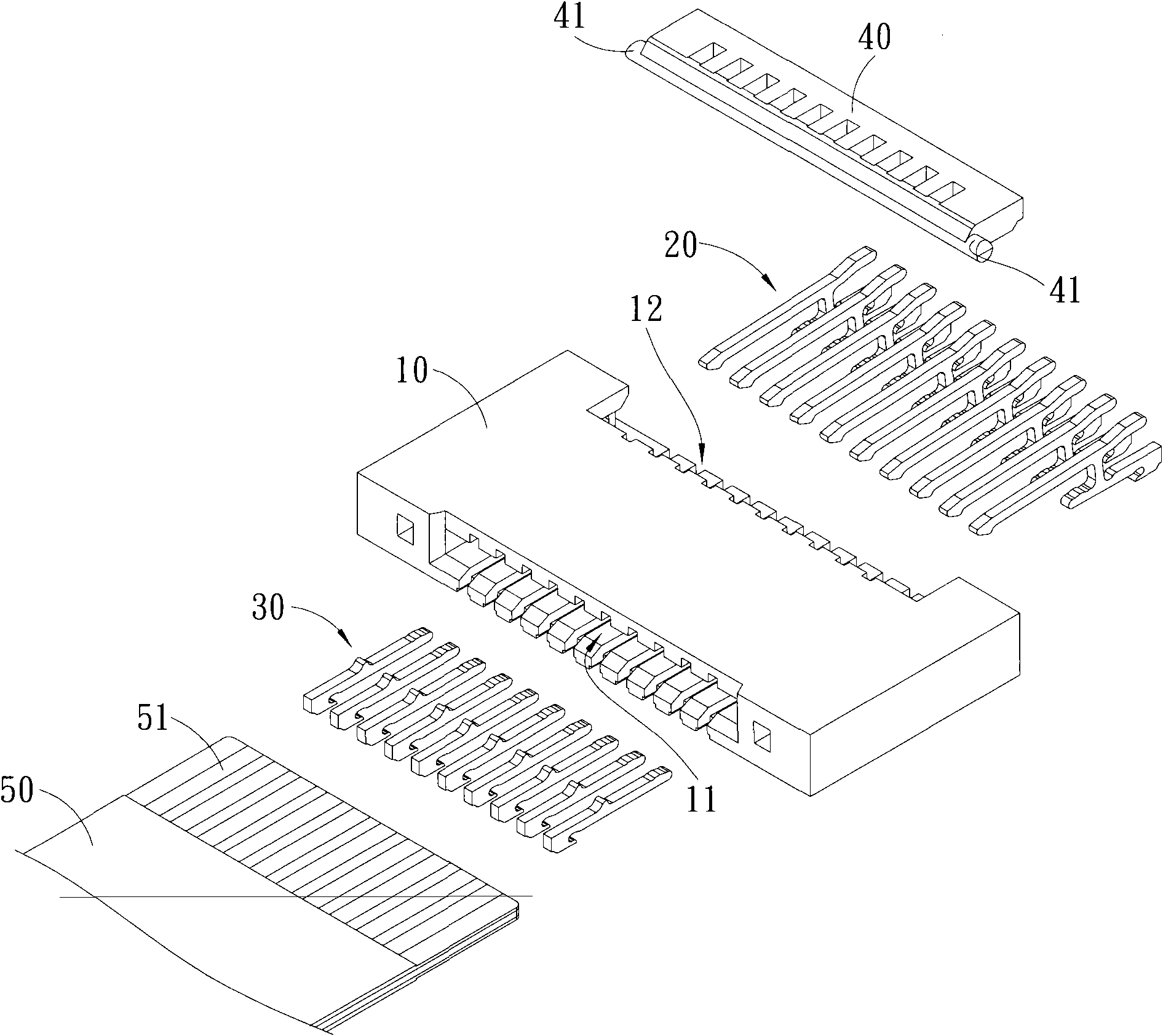
[0029] Please refer to Figure 1 to Figure 4 , are schematic diagrams of preferred embodiments of the present invention. In this preferred embodiment, a flip-back electrical connector is taken as an example for illustration, but the applicable forms of the present invention are not limited to flip-back connectors.

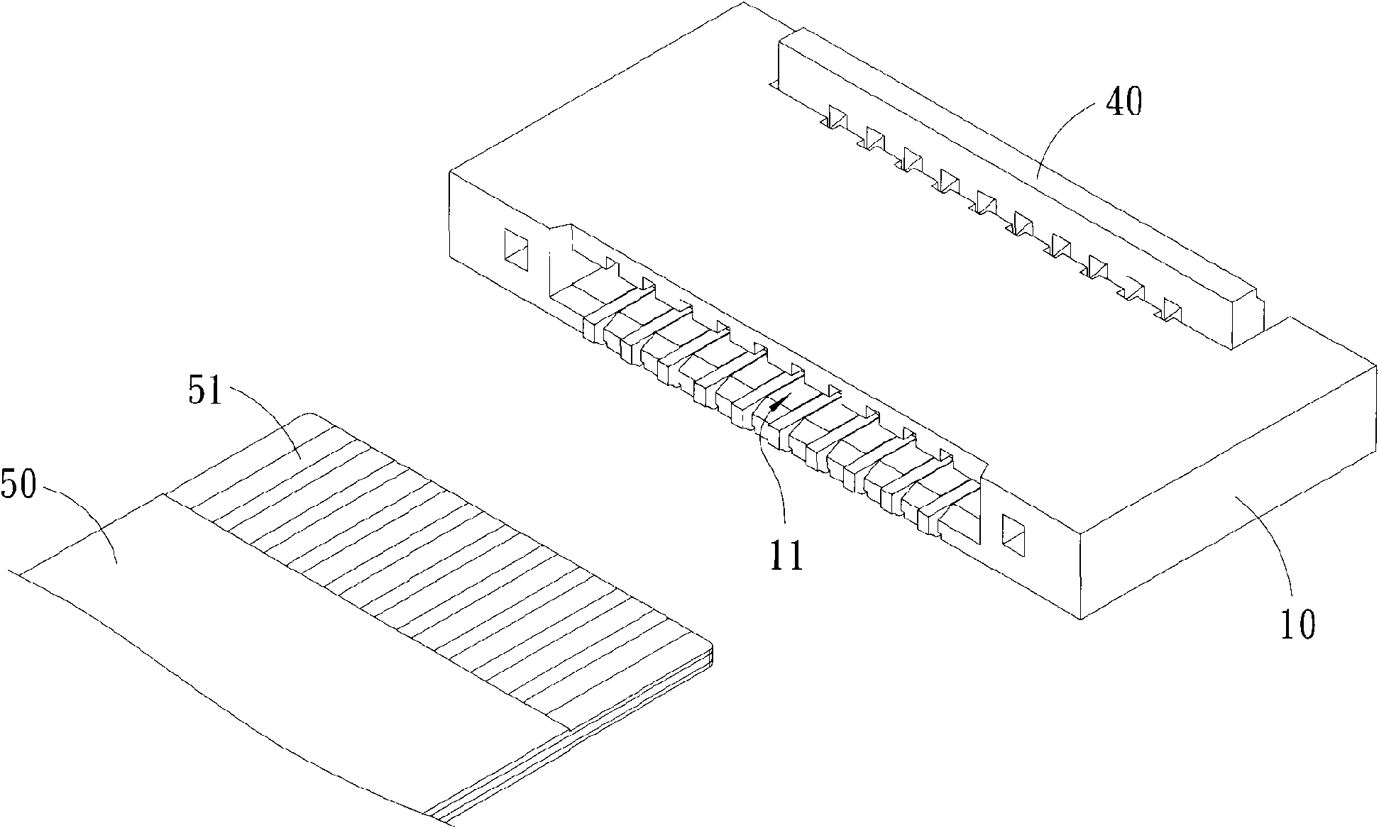
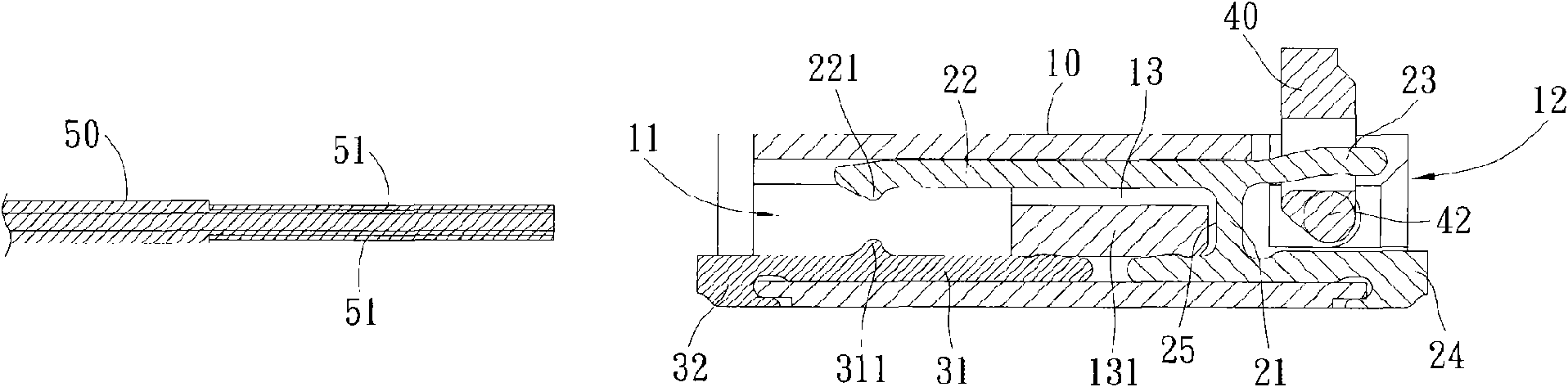
[0030] Please refer to figure 1 and figure 2 Shown is an exploded view and an assembly view of the flip-back electrical connector of this preferred embodiment, which is composed of an insulating body 10, a plurality of first terminals 20, a plurality of second terminals 30 and a rotating member 40 , for connecting the flexible cable 50. The following describes the structural composition of each component:

[0031] The insulating body 10 has a long rectangular structure, and its opposite sides are respectively provided with a front opening 11 and a rear opening 12. The front opening 11 can be inserted into one end of the flexible cable 50. The insulating body 10...


PUM


Abstract

The invention relates to an electric connector combination, which at least comprises an insulating body, complex first terminals, complex second terminals and a flexible flat cable, wherein the insulating body is provided with complex terminal slots, and the first terminals and the second terminals are simultaneously assembled in the terminal slots and extended along the inner surfaces at two sides of the terminal slots respectively so that upper contact points of the first terminals and lower contact points of the second terminals are opposite vertically; and double surfaces of the flexible flat cable are provided with conductive contact points which can form electrically conductive connections with the upper contact points of the first terminals and the lower contact points of the second terminals respectively.

Description

technical field [0001] The present invention relates to an electrical connector combination, especially an electrical connector combination that can cooperate with a flexible cable with double-sided conductive contacts. Background technique [0002] The traditional electrical connector used to connect flexible cables, such as the technology disclosed in US Pat. The flexible cable is fixed by a freely rotatable pressure member. In this type of electrical connector, the upper arm of the terminal is mostly used to support the rotation of the pressure member, while the lower arm of the terminal can be used to contact the conductive contact of the flexible cable. . Since all conductive contacts are formed on a single surface, when the number of conductive contacts required by the system is low, the width of the electrical connector is required to be low, which will not affect production, but when the number of conductive contacts required by the system When the number increases...

Claims


Application Information

Patent Timeline
Patent Type & Authority Applications(China)
IPC IPC(8): H01R12/24H01R13/629H01R12/38H01R12/77
Inventor 王建淳官东庆
Owner DACHANG ELECTRONICS TECH SUZHOU CO LTD
Why Eureka
Try Eureka