Ultrasonic sensor

一种传感器、超声波的技术,应用在超声波传感器领域,能够解决不能有效地降低余响振动本身等问题,达到好分辨能力、降低余响振动的效果

Active Publication Date: 2009-09-09
MURATA MFG CO LTD
View PDF3 Cites 10 Cited by
  • Summary
  • Abstract
  • Description
  • Claims
  • Application Information

AI Technical Summary

Problems solved by technology

However, this ultrasonic sensor cannot effectively reduce the reverberation vibration itself transmitted to the side wall portion of the housing

Method used


Image

  • Ultrasonic sensor
  • Ultrasonic sensor
  • Ultrasonic sensor

Examples


Embodiment 1

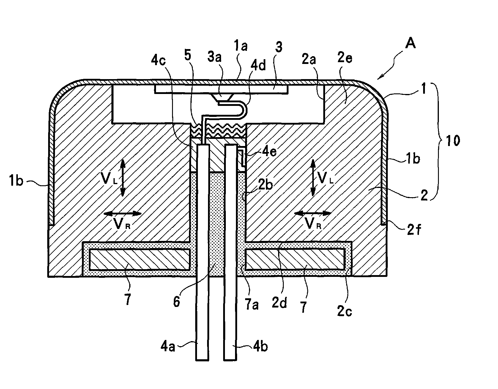
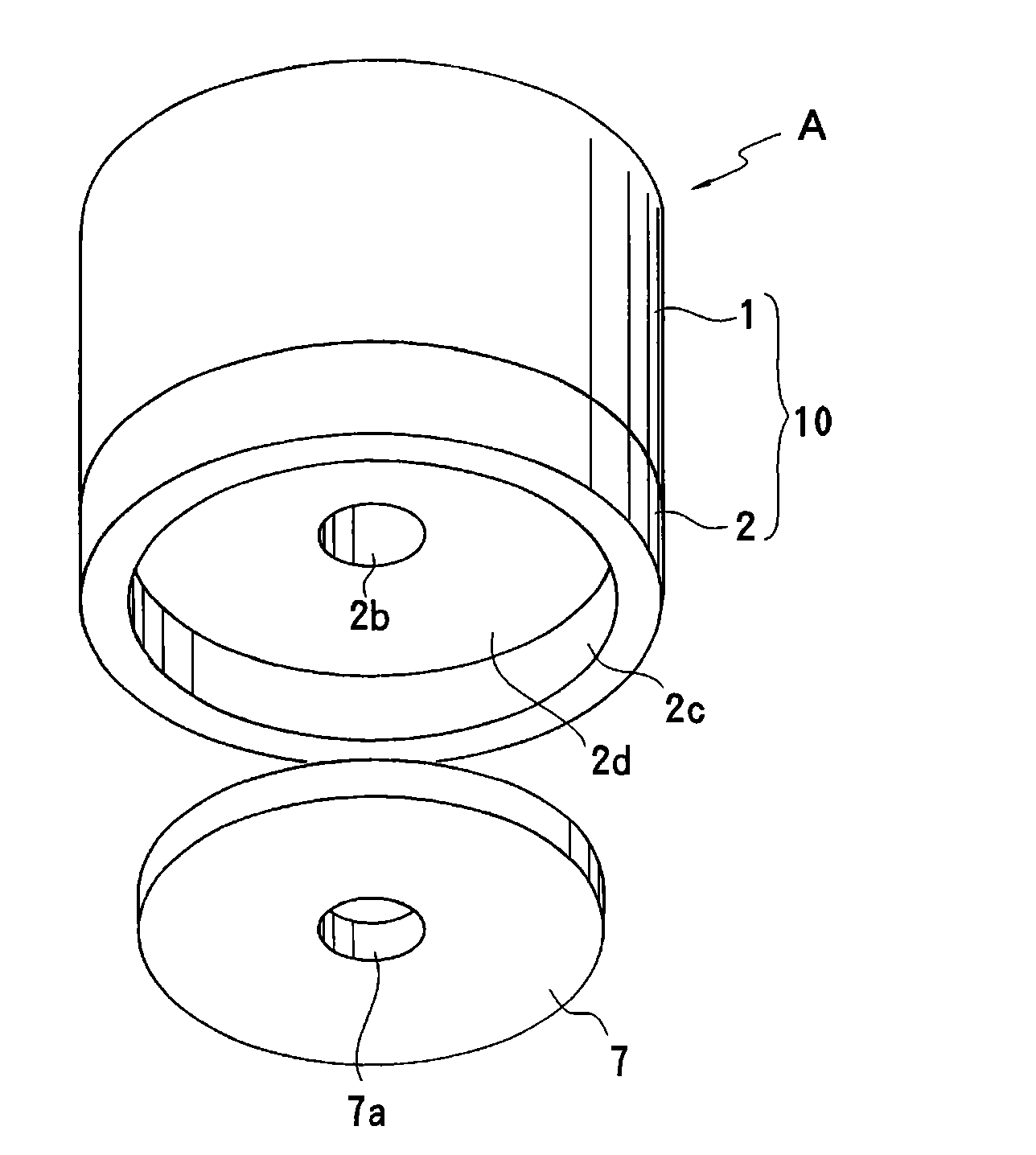
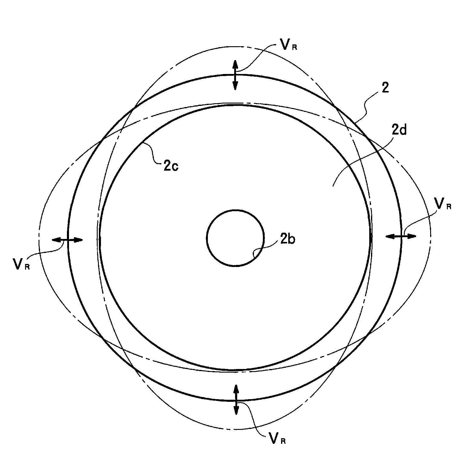
[0063] figure 1 and figure 2 The ultrasonic sensor of Example 1 according to one embodiment of the present invention is shown. This ultrasonic sensor A includes an outer case 1 , an inner case 2 , a piezoelectric element 3 , metal terminals 4 a and 4 b , an acoustic wave absorber 5 , a filler 6 , and a flat member 7 .

[0064] The outer case 1 is formed by punching a metal plate to have a bottomed cylindrical shape (U-shape in cross-sectional view), and a disc-shaped piezoelectric element 3 is fixed to the inside of the bottom 1a of the outer case to constitute a single piezoelectric vibrator. The piezoelectric element 3 includes a piezoelectric ceramic plate and electrodes formed on top and bottom surfaces of the piezoelectric ceramic plate, and when a voltage is applied between the electrodes, the piezoelectric element 3 vibrates in its radial or thickness direction. The outer case 1 includes a cylindrical side wall portion 1b having an opening at a position adjacent to ...

Embodiment 2

[0077] Figure 6 An ultrasonic sensor according to Example 2 of one embodiment of the present invention is shown. In this ultrasonic sensor B, the entire rear surface of the inner case 2A serves as a flat portion 2d on which a flat member 7 is disposed so as to oppose the flat portion 2d with a filler 6 therebetween. The outer diameter of the flat member 7 is substantially the same as that of the inner case 2A. The same components as those in Embodiment 1 are denoted by the same reference numerals, and repeated descriptions are omitted.

[0078] In this embodiment, compared with Embodiment 1, the areas of the inner case 2A and the flat plate 7 facing each other increase toward the outer periphery. Therefore, the shear deformation acting on the filler 6 is more effective. That is, since the deformation of the outer peripheral portion of the flat portion 2d of the inner case 2A is larger than that of the inner peripheral portion thereof, the filler 6 located between the outer...

Embodiment 3

[0080] Figure 7 The ultrasonic sensor of Example 3 according to one embodiment of the present invention is shown. The same components as those in Embodiment 1 are denoted by the same reference numerals, and repeated descriptions are omitted. In the ultrasonic sensor C of the present embodiment, the lead wire 4g is connected to the rear surface of the piezoelectric element 3 fixed to the inner side of the bottom 1a of the outer case 1, and the other lead wire 4h is connected to the inner case 2B The inner surface of the central hole 2d. The lead wires 4g and 4h extend to the outside through the central hole 2b and the through-hole 7a of the plate member 7 . In this embodiment, flat piece 7 is accommodated in recess 2c formed at the rear end of inner case 2B, and filler 6 is filled between flat portion 2d as the bottom surface of concave portion 2c and flat piece 7. When the inner shell 2B vibrates, relative deformation occurs between the inner shell and the flat member 7, a...


PUM


Abstract

The present invention provides an ultrasonic sensor having an enhanced obstacle shortest detection distance resolution by attenuating the unwanted vibration of the sides of the case and reducing the reverberating time. A piezoelectric element (3) is fixed to the inside surface of the bottom (1a) of a bottomed cylindrical outer case (1). An annular inner case (2) having a center hole (2b) extending in the axial direction inside the side wall of the outer case (1). A flat part (2d) is provided around the center hole (2b) of the inner case (2). A viscoelastic filler (6) is placed in the center hole (2b) to the flat part(2d). Plate members (7) are opposed on the flat part (2d), with the filler (6) interposed therebetween. When the inner case (2) vibrates, the plate members (7) hardly vibrate and therefore the filler (6) sandwiched between the flat part (2d) and the plate members (7) shear-deform, and the vibration is suppressed by the viscoelastic attenuation action.

Description

technical field [0001] The present invention relates to ultrasonic sensors, and in particular, to ultrasonic sensors used as, for example, obstacle detection sensors such as vehicle rear sonar devices and corner sensors. Background technique [0002] Ultrasonic sensors capable of emitting and receiving ultrasonic waves have been used as obstacle detection sensors such as rear sonar devices in vehicles. Such as Figure 15 As shown, such an ultrasonic sensor includes a cylindrical housing 100 with a bottom, and a piezoelectric element 101 is attached to the inner side of the bottom of the housing, so that the bottom of the housing 100 functions as a vibrating surface. A terminal holder 104 supporting the metal terminals 102 and 103 is fixed inside the housing 100 , and a viscoelastic filler 105 is filled in a recess formed by the terminal holder 104 and the side walls of the housing 100 . The sound absorbing body 106 is provided inside the terminal holder 104 (adjacent to the...

Claims


Application Information

Patent Timeline
Patent Type & Authority Applications(China)
IPC IPC(8): H04R17/00G01S15/931
CPCG10K9/22G10K9/122G01S15/931G01S7/521B60R21/00G01H11/08
Inventor 村田好司小谷将人浅田隆昭岛本隆之平野裕幸古谷未央
Owner MURATA MFG CO LTD
Why Eureka
Try Eureka