Fly wheel type composite damper for transmission shafting

A transmission shaft and damper technology, applied in the field of dampers, can solve the problems of increasing research cost and occupying space, and achieve the effects of saving cost, saving space and improving vibration damping ability

Inactive Publication Date: 2009-02-11
NANJING UNIV OF AERONAUTICS & ASTRONAUTICS
View PDF1 Cites 12 Cited by
  • Summary
  • Abstract
  • Description
  • Claims
  • Application Information

AI Technical Summary

Problems solved by technology

In the research, people often pay more attention to torsional vibration, and have studied a variety of torsional vibration dampers, including various pendulum torsional vibration dampers, viscous fluid dampers and magnetorheological fluid dampers, and also have methods to control their lateral vibrations. The damping device, like the shaft damper described in patent CN 1620563A, is rarely involved in the damping device for its longitudinal vibration, and at present, various vibration control devices for the shaft system are studied separately, which increases the research cost and require more space

Method used


Image

  • Fly wheel type composite damper for transmission shafting
  • Fly wheel type composite damper for transmission shafting
  • Fly wheel type composite damper for transmission shafting

Examples


Embodiment Construction

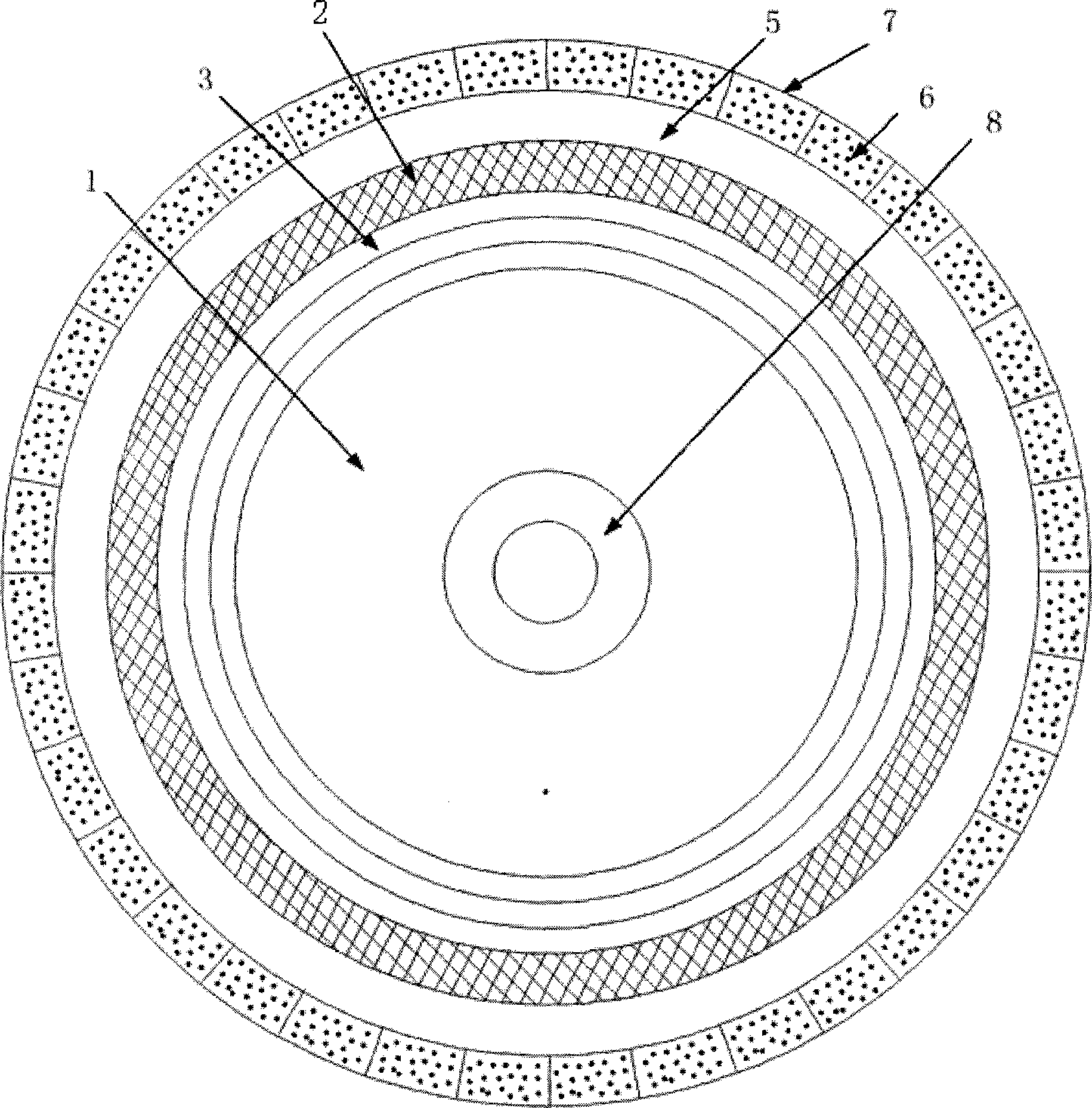
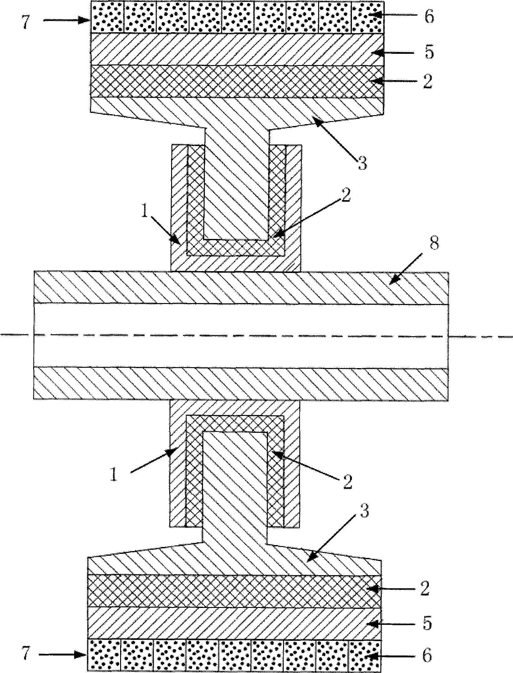
[0012] Such as figure 1 , 2 As shown, the drive shaft system flywheel compound damper of the present invention includes a cross-section mounted on the shaft type of constraining flange 1, also includes a cross-section Type 2 hub, the constraining flange is set on the shaft, the hub is installed in the groove of the constraining flange through its inner ring, and the inner ring of the hub and the inner wall of the constraining flange groove are provided with a viscoelastic damping layer, and the outer ring of the hub It is connected with the inner ring of the flywheel 5 through another viscoelastic damping layer, and the outer ring of the flywheel is also equipped with a damping layer 7 of a honeycomb structure filled with damping particles 6 inside. The damping particles 6 are filled in the cavity of the honeycomb structure with a certain filling rate.

[0013] When the torsional vibration occurs in the shafting, the viscoelastic damping layer between the flywheel 5 and t...


PUM


Abstract

The invention relates to a transmission shafting flywheel-type composite damper, in particular to a shafting vibration control damper. The invention is characterized in that: the shafting vibration control damper comprises a restriction flange (1) which is arranged on a shaft and further includes a hub (2); the restriction flange is sheathed on the shaft, the hub is mounted in a groove of the restriction flange by an inner ring thereof, the inner ring of the hub and the inner side wall of the groove of the restriction flange are provided with a viscoelastic damping layer, an outer ring of the hub is connected with an inner ring of a flywheel (5) by another viscoelastic damping layer, an outer ring of the flywheel is further provided with a damping layer (7) which is internally filled with damping particles (6) and is of honeycomb structure. The shafting vibration control damper can control torsional vibration, longitudinal vibration and transverse vibration of the shafting at the same time and can effectively save cost and space.

Description

technical field [0001] The present invention relates to a damper, in particular to a shafting vibration control damper. Background technique [0002] The shafting of the transmission system of ships and other large-scale institutions is prone to vibration due to the excitation of power equipment and propellers, and its vibration form is multi-directional, that is, torsional vibration, longitudinal vibration and lateral vibration exist at the same time. In the research, people often pay more attention to torsional vibration, and have studied a variety of torsional vibration dampers, including various pendulum torsional vibration dampers, viscous fluid dampers and magnetorheological fluid dampers, and also have methods to control their lateral vibrations. The damping device, like the shaft damper described in patent CN 1620563A, is rarely involved in the damping device for its longitudinal vibration, and at present, various vibration control devices for the shaft system are st...

Claims


Application Information

Patent Timeline
Patent Type & Authority Applications(China)
IPC IPC(8): F16F15/12
Inventor 陈前段勇
Owner NANJING UNIV OF AERONAUTICS & ASTRONAUTICS
Why Eureka
Try Eureka