Threshing apparatus

A threshing and drum technology, applied in threshing equipment, agriculture, applications, etc., can solve the problems of deterioration of threshing efficiency and easy retention of untreated materials in the drum chamber, and achieve the effect of improving threshing efficiency and reducing the opening rate.

Active Publication Date: 2009-09-16
YANMAR POWER TECHNOLOGY CO LTD
View PDF1 Cites 5 Cited by
  • Summary
  • Abstract
  • Description
  • Claims
  • Application Information

AI Technical Summary

Problems solved by technology

[0010] However, since the above-mentioned receiving net is formed by punching, even if the size of the punching hole is increased, the ratio of the opening area of ​​the entire punching hole to the area of ​​the entire receiving net will be increased from the viewpoint of strength or processing accuracy. There is also a limit to the ratio (aperture ratio)
[0011] On the other hand, in the receiving net described in the above-mentioned patent document 2, a plurality of openings are formed by the above-mentioned plurality of vertical plate members and the above-mentioned plurality of steel wire members. The above opening ratio can be increased, but on the contrary, the above-mentioned lumpy untreated matter tends to stay in the drum chamber, and as a result, there is a problem that the threshing efficiency deteriorates.

Method used


Image

  • Threshing apparatus
  • Threshing apparatus
  • Threshing apparatus

Examples


Embodiment approach 1

[0058] Hereinafter, 1st Embodiment of the threshing apparatus which concerns on this invention is demonstrated referring drawings.

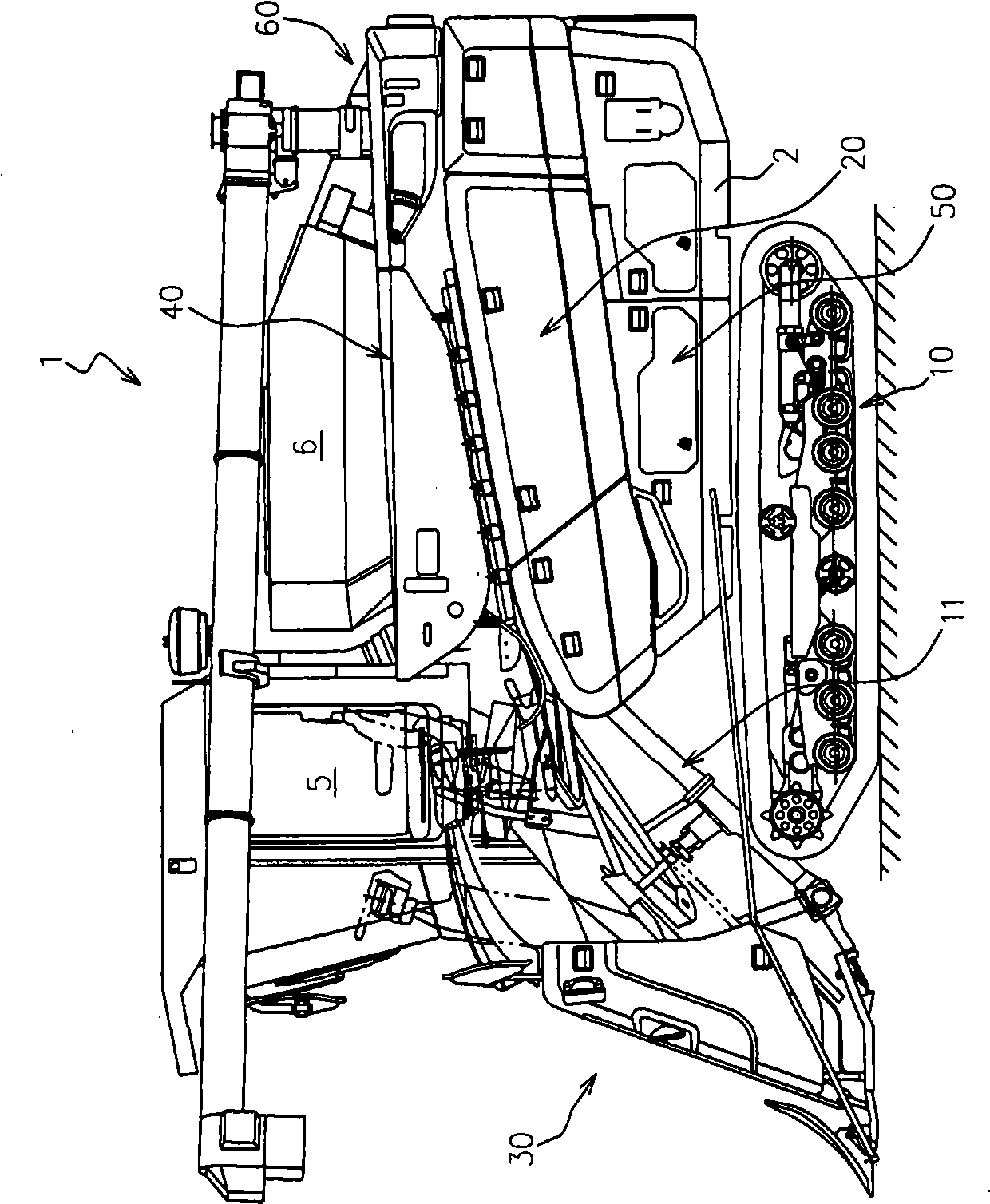
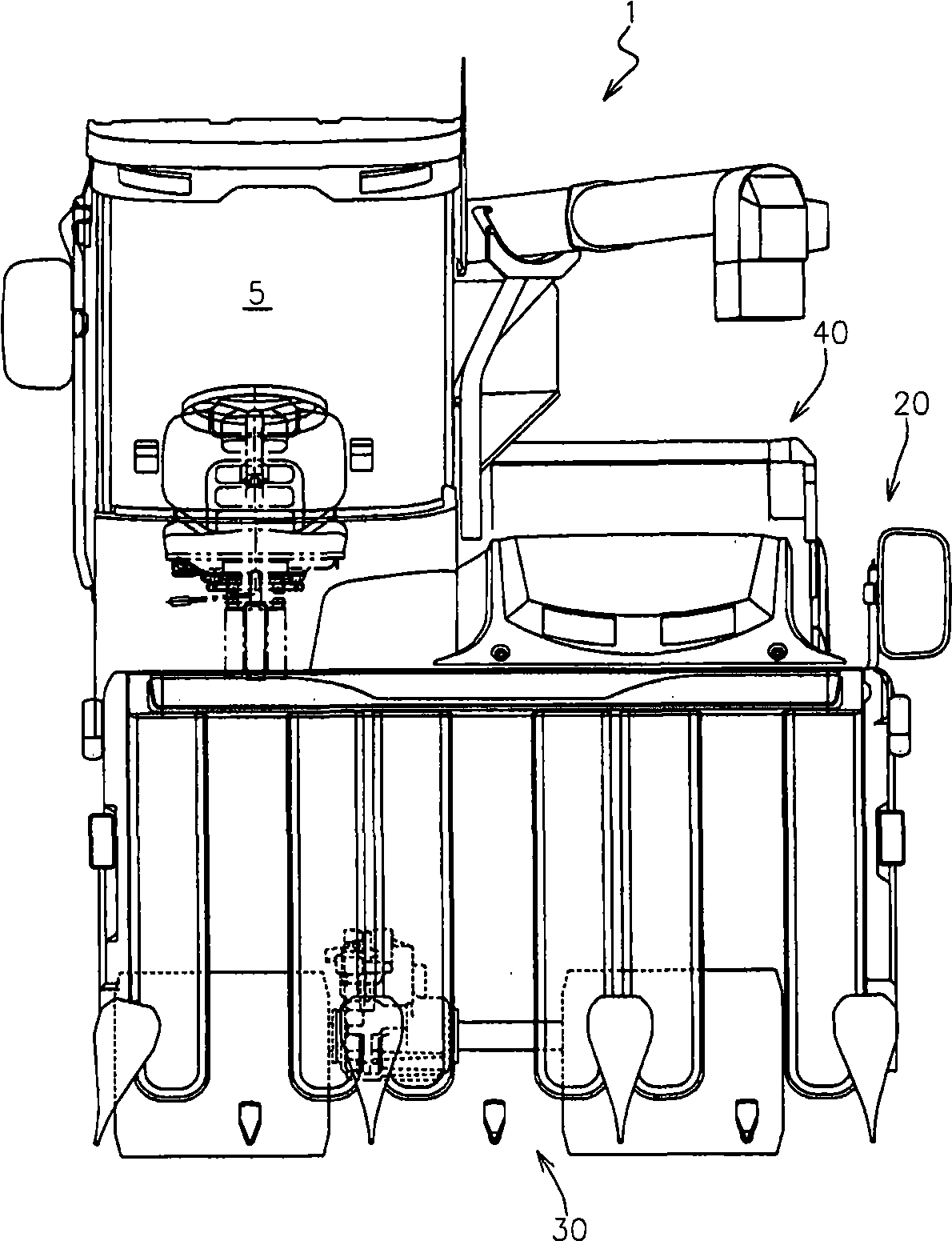
[0059] figure 1 and figure 2 It is a left side view and a top view of the combine 1 to which the threshing apparatus concerning 1st Embodiment was applied.

[0060] Such as figure 1 and figure 2Shown, above-mentioned combine harvester 1 possesses: main frame 2; Engine (not shown) as the power source supported on the above-mentioned main frame 2; It is a crawler-type traveling device) 10; in front of the above-mentioned main frame 2, a harvesting device 30 that is arranged on a harvesting frame 11 liftably supported on the main frame 2; 2, the feeding chain device 20 conveyed in the rear direction of the left side; the threshing device 40 arranged on the left part of the above-mentioned main frame 2 so as to carry out threshing treatment to the straw conveyed by the above-mentioned feeding chain device 20; The sorting device 50 below the ab...

Embodiment approach 2

[0133] The threshing apparatus 40B which concerns on 2nd Embodiment of this invention is demonstrated below.

[0134] Figure 6 It shows the front schematic view of the threshing apparatus 40B which concerns on this 2nd Embodiment, Figure 7 express Figure 6 Shown is an expanded view of the receiving wire 44B in the above threshing device. In addition, in Figure 7 In , the positional relationship among the said receiving net 44B, the threshing cylinder 43, and the dust-feeding port processing cylinder 46 is shown together.

[0135] In addition, in the drawings, the same reference numerals are assigned to the same components as those in the above-mentioned first embodiment, and their detailed descriptions are appropriately omitted.

[0136] In this embodiment, if Figure 6 and Figure 7 As shown, the above-mentioned receiving net 44B is equipped with: viewed in the direction of the rotation axis of the threshing cylinder 43, it is made into an arc shape so as to cover t...


PUM


Abstract

The present invention discloses a threshing apparatus, which is provided with a receiving network under a threshing roller; one rear side of a roller room that collects the threshing roller communicates with a front side of a processing room that collects a dust sending port processing roller through the dust sending port, which is capable of enhancing threshing efficiency of the threshing roller, and is capable of transporting substance unprocessed by the threshing roller from the roller room to the processing room in high efficiency. In a first receiving network (71) of a receiving network (44) that located on one front side of the dust sending port (47), a plurality of longitudinal panel components (73) with plate surface facing front and back along the threshing roller (43). A plurality of linear components (74) seen from a cross section view are in circular shape roughly, in a state of alternating on holes (73a) of the longitudinal panel components (73) along axial direction of the threshing roller (43), and are arranged along circumferential direction of the threshing roller (43).

Description

technical field [0001] This invention relates to the threshing apparatus provided with the threshing cylinder and the dust delivery port processing cylinder, and arrange|positioning the receiving net in the lower periphery of the said threshing cylinder. Background technique [0002] As a receiving net suitable for a threshing device, someone has proposed a scheme in which a plurality of openings are formed on a flat plate member by press processing (for example, refer to Japanese Patent No. 3846886, hereinafter referred to as Patent Document 1) , or by a plurality of longitudinal plate members along the circumferential direction of the threshing cylinder and a plurality of wire pieces along the axial direction of the threshing cylinder to form a scheme of receiving nets consisting of a plurality of openings (for example, refer to Japanese Patent Application No. 11-253044 publication, hereinafter referred to as Patent Document 2). [0003] However, as a receiving net suitab...

Claims


Application Information

Patent Timeline
Patent Type & Authority Applications(China)
IPC IPC(8): A01F12/395A01F12/18A01F12/44
Inventor 宫本彰稻垣晴三
Owner YANMAR POWER TECHNOLOGY CO LTD
Why Eureka
Try Eureka