Transmission shaft monitoring device and threshing drum shaft monitoring device

A technology for monitoring devices and threshing drums, applied in threshing equipment, applications, agricultural machinery and implements, etc., can solve the problems of reduced measurement accuracy, high cost, and complex structure of rotational speed or torque sensors, so as to avoid signal acquisition errors and improve work efficiency. Efficiency and the effect of reducing measurement error

Active Publication Date: 2019-02-19
JIANGSU UNIV
View PDF7 Cites 4 Cited by
  • Summary
  • Abstract
  • Description
  • Claims
  • Application Information

AI Technical Summary

Problems solved by technology

The above-mentioned structure is complex, expensive, and there are many interference signals. In addition, due to the torsional vibration of the threshing drum shaft, the measurement accuracy of the rotational speed or torque sensor will be greatly reduced, and the complex working environment will lead to distortion of the measurement signal and reduced reliability.

Method used


Image

  • Transmission shaft monitoring device and threshing drum shaft monitoring device
  • Transmission shaft monitoring device and threshing drum shaft monitoring device
  • Transmission shaft monitoring device and threshing drum shaft monitoring device

Examples


Embodiment Construction

[0049] The present invention will be further described below in conjunction with the accompanying drawings and specific embodiments, but the protection scope of the present invention is not limited thereto.

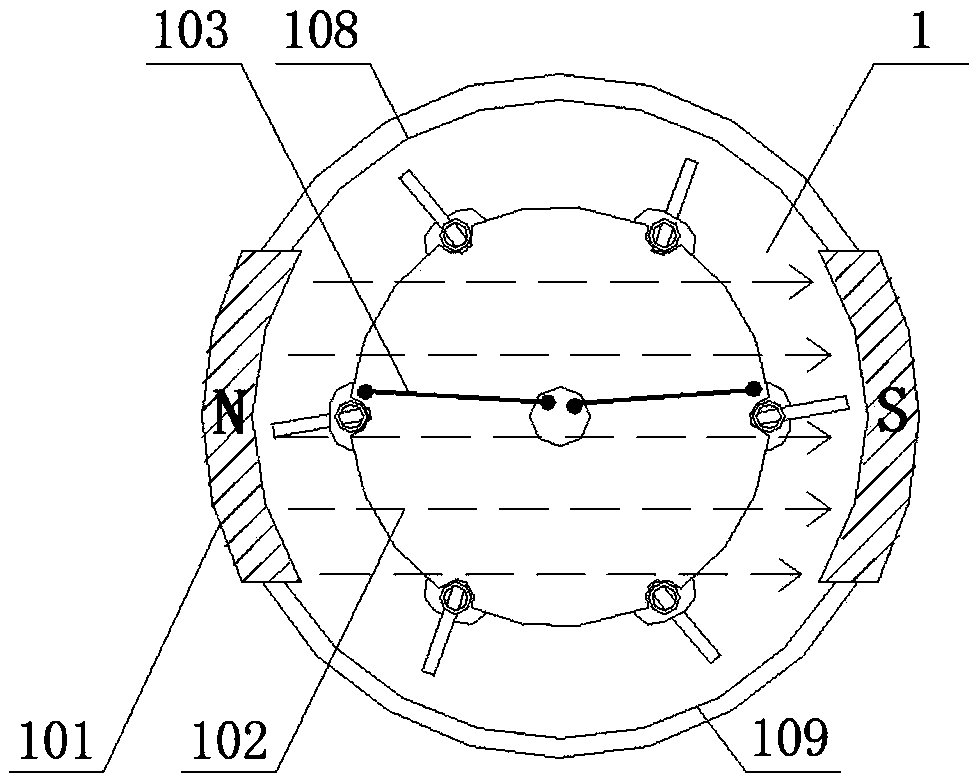
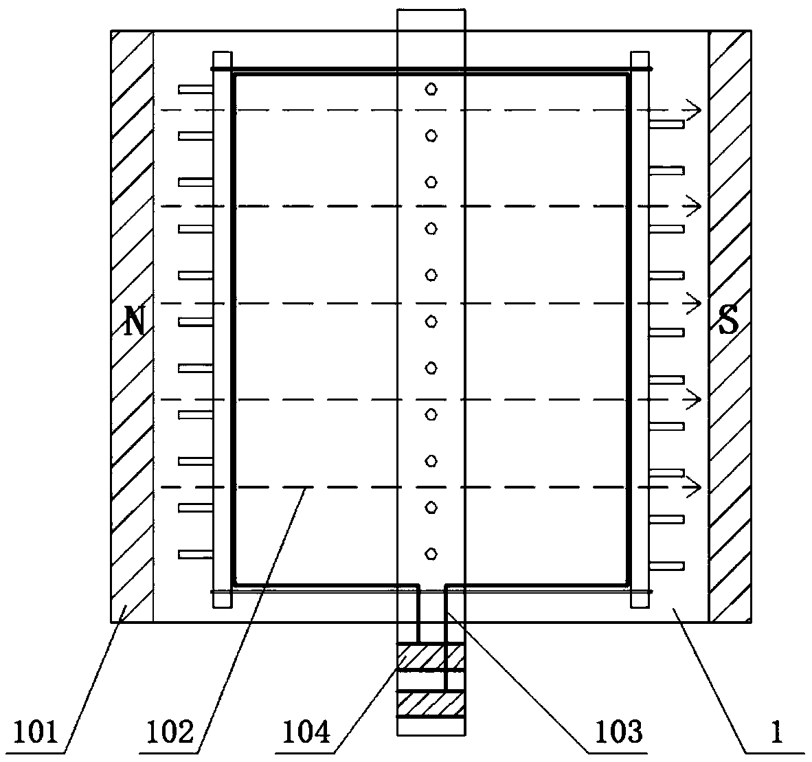
[0050] Such as figure 1 and figure 2 As shown, the transmission shaft monitoring device described in the present invention includes an electromagnetic induction signal generating device 1 and a control system; the electromagnetic induction signal generating device 1 is used to be installed on the shaft end of the transmission shaft, and is used to detect the vibration generated by the rotation of the transmission shaft voltage change signal;

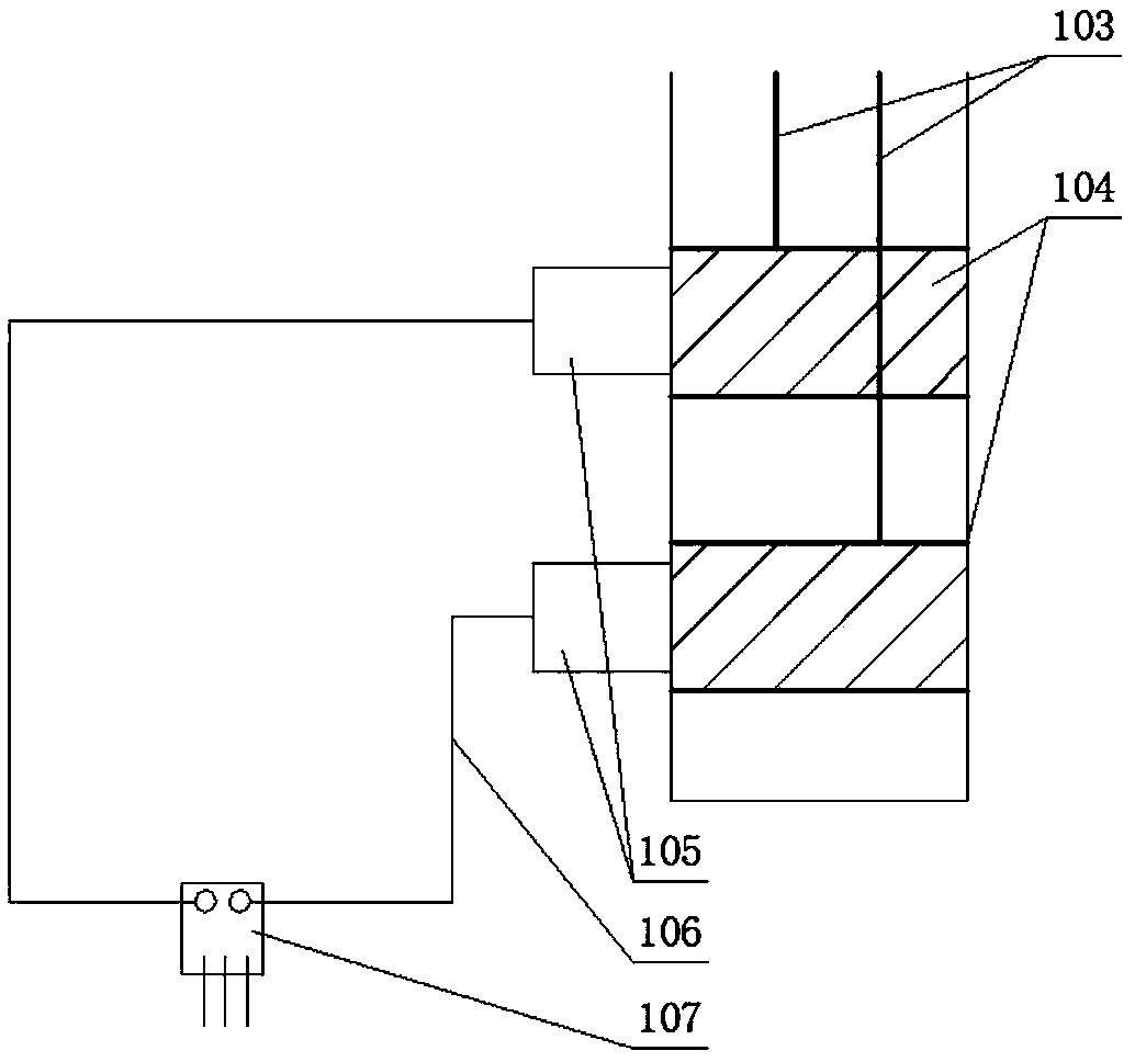
[0051] Such as image 3 As shown, the electromagnetic induction signal generating device 1 includes a magnetic pole pair 101, a coil 103, a metal ring 104, a brush 105 and a voltage sensor 107; the magnetic pole pair 101 is used to generate a magnetic field at the transmission shaft end; the transmission shaft end Fix the coil 1...


PUM


Abstract

The invention provides a transmission shaft monitoring device. The transmission shaft monitoring device comprises an electromagnetic induction signal generation device and a control system; the electromagnetic induction signal generation device is used for detecting a voltage change signal generated by the rotation of a transmission shaft; the control system is used for analyzing and judging the voltage change signal input by the electromagnetic induction signal generation device. The electromagnetic induction signal generation device comprises a magnetic pole pair, a coil, metal rings, electric brushes and a voltage sensor; the magnetic pole pair is used for generating a magnetic field on a transmission shaft end; the coil is fixed on the end face of the transmission shaft and used for cutting magnetic force lines; the two metal rings are arranged at the shaft ends of the transmission shaft and not in contact with each other; the two ends of the coil are connected with the two metal rings respectively; the two electric brushes are in contact with the two metal rings respectively, and the two electric brushes and the voltage sensor form a closed circuit. The transmission shaft monitoring device can analyze the voltage amplitude and cycle which are output by the voltage sensor and monitor whether or not the state of the transmission shaft meets the design requirement.

Description

technical field [0001] The invention relates to the field of vibration detection or the field of vibration monitoring of combine harvesters, in particular to a transmission shaft monitoring device and a threshing drum shaft monitoring device. Background technique [0002] The working environment of the combine harvester is harsh and the working conditions are complicated, so the threshing drum often has problems such as grain blockage and speed drop. If the driver fails to detect and deal with it in time, excessive feeding and low speed will lead to poor grain threshing. Clean, thereby wasting a large amount of food, and the threshing efficiency of the threshing drum is also greatly reduced. Therefore, in order to effectively improve the working efficiency and threshing efficiency of the combine harvester threshing cylinder, it is of great significance to monitor the working state of the threshing cylinder in real time. [0003] At present, the devices and methods for monit...

Claims


Application Information

Patent Timeline
Patent Type & Authority Applications(China)
IPC IPC(8): A01F12/58
CPCA01F12/58
Inventor 唐忠周跃鹏张浩天李耀明李宇
Owner JIANGSU UNIV
Why Eureka
Try Eureka