Thrashing drum

A technology for threshing drums and threshing parts, which is applied in threshing equipment, applications, agricultural machinery and implements, etc. It can solve the problems of low grain threshing efficiency, cumbersome disassembly, and large driving load, so as to maximize threshing efficiency, improve threshing efficiency, Meticulous effect of the threshing process

Inactive Publication Date: 2011-08-10
XENITH TRACK
View PDF5 Cites 4 Cited by
  • Summary
  • Abstract
  • Description
  • Claims
  • Application Information

AI Technical Summary

Problems solved by technology

[0006] However, the threshing drum 100 used for the threshing machine as mentioned above is heavy because the drum body 110 is cylindrical, and it is not only cumbersome to install or disassemble from the threshing machine, but also quite inconvenient to use. It can also lead to the problem of large driving load
[0007] In addition, the multiple threshing blades 112 formed from one side to the other side of the outer surface of the drum body 110 have the problem of low grain threshing efficiency due to their relatively simple arrangement.

Method used


Image

  • Thrashing drum
  • Thrashing drum
  • Thrashing drum

Examples


Embodiment Construction

[0032] Hereinafter, preferred embodiments of the threshing cylinder according to the present invention will be described in detail with reference to the accompanying drawings.

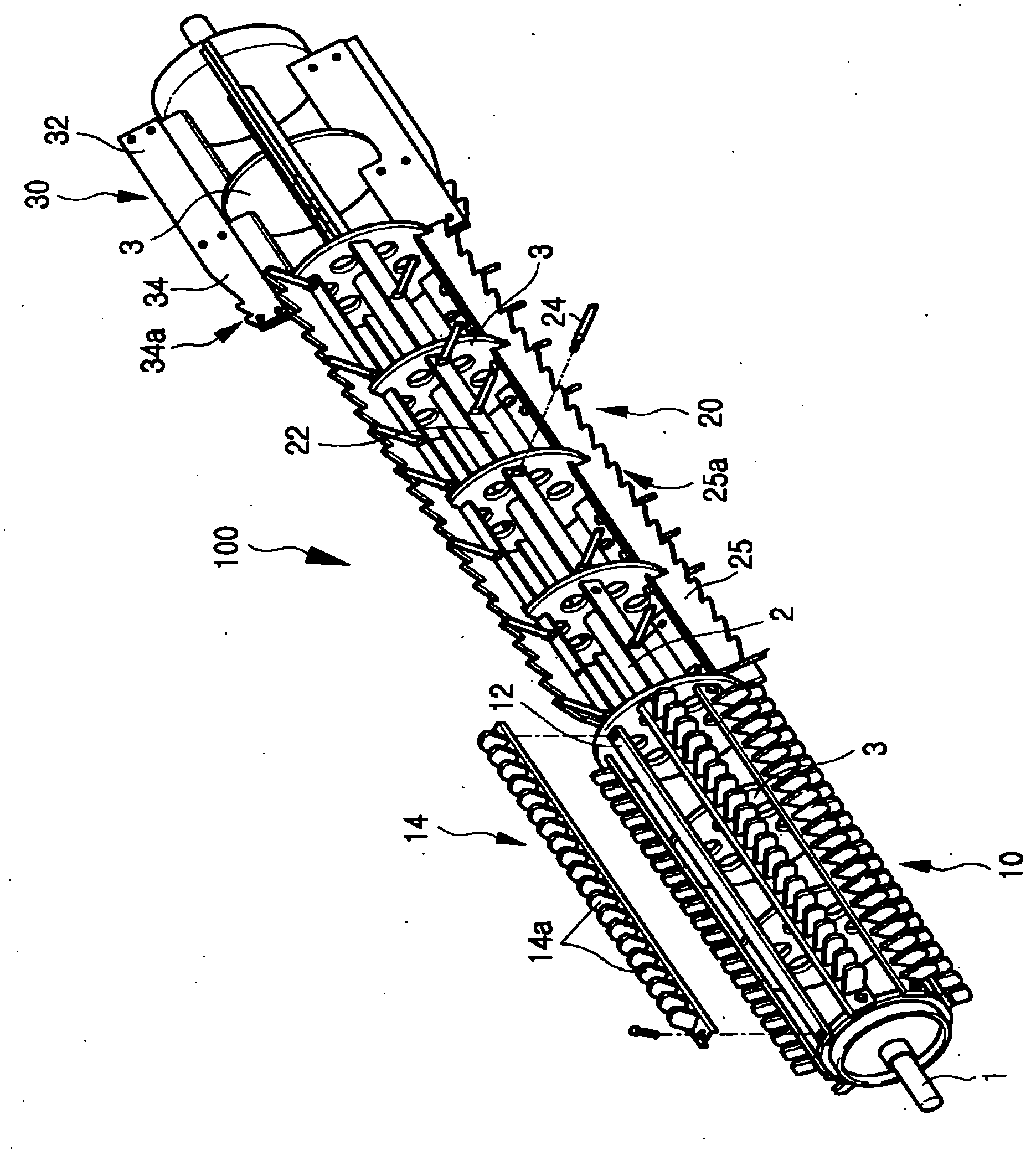
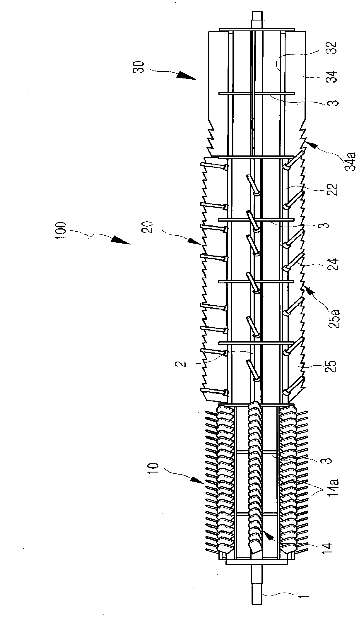
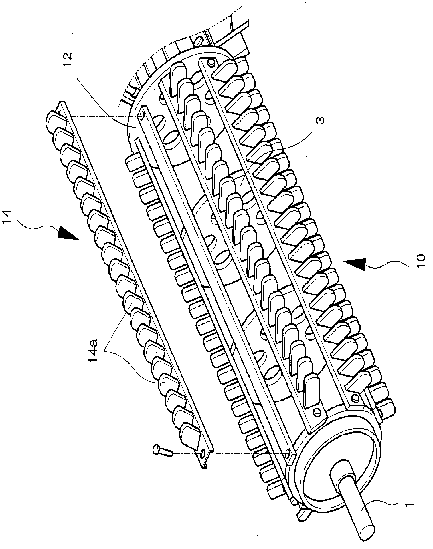
[0033] figure 2 is a perspective view schematically showing a main part of a threshing drum according to an embodiment of the present invention, image 3 It is a main part front view which schematically shows the threshing drum which concerns on one Embodiment of this invention.

[0034] Such as figure 2 and image 3 As shown, the threshing cylinder according to an embodiment of the present invention includes: a shaft rod 2 , a plurality of support plates 3 , a primary threshing part 10 , a secondary threshing part 20 , and a discharge part 30 .

[0035] Although not shown, a threshing drum according to an embodiment of the invention is installed on a conventional threshing machine for threshing grain.

[0036] Mounting shafts 1 for receiving rotational force are formed on both sides of the shaft...


PUM


Abstract

The present invention relates to a thrashing drum (100) that can maximize thrashing efficiency while minimizing load occurring when the drum is rotated in a trashing process. The thrashing drum (100) includes a shaft (2) having axle portions formed on its both sides, a plurality of support plates (3) formed on the shaft (2) at specific intervals, a primary thrashing unit configured to primarily separate ears and corns from stems or branches of crops input thereto and that is disposed in the support plates, a secondary thrashing unit configured to secondarily separate by blowing ears and corns that have not been thrashed in the primary thrashing unit and that is disposed in the support plates, and a discharge unit configured to thirdly discharge the stems or branches that have been thrashed and that is disposed in the support plates (3).

Description

technical field [0001] The invention relates to a threshing cylinder installed on a threshing machine, and more particularly relates to a threshing cylinder which minimizes the load generated during rotation during the threshing process, thereby maximizing the threshing effect. Background technique [0002] A thresher is a kind of agricultural machinery, which contacts the ears of crops fed through the rotating threshing drum, thereby cutting off the parts of the ears or hitting the grains, and then separating the ears and grains from the grain stalks. [0003] Such as figure 1 As shown, the threshing drum 100 of the conventional threshing machine consists of a cylindrical drum body 110, threshing blades 112 arranged in rows from one side of the outer surface of the drum body 110 to the other side, and arranged on both sides of the drum body 110. Side and is used to receive the installation shaft 114 of rotating force. [0004] In the conventional threshing drum 100 having...

Claims


Application Information

Patent Timeline
Patent Type & Authority Applications(China)
IPC IPC(8): A01F7/06A01F12/18
CPCA01F11/06A01F12/22
Inventor 崔镕宰
Owner XENITH TRACK
Why Eureka
Try Eureka