
A hose depoling method and a device thereof

A rubber tube and core removal technology, which is applied in the field of rubber tube core removal methods and devices thereof, achieves the effects of solving core removal difficulties, high efficiency and simple structure

Active Publication Date: 2009-09-16
北京腾龙天元橡塑有限公司
View PDF0 Cites 16 Cited by
  • Summary
  • Abstract
  • Description
  • Claims
  • Application Information

AI Technical Summary

Problems solved by technology

[0005] In view of the problems existing in the existing situation, the purpose of this utility model is to provide a rubber hose core removal method and its device which are simple in the way of removing the rubber hose and are suitable for multi-corrugated and long-length rubber hoses.

Method used

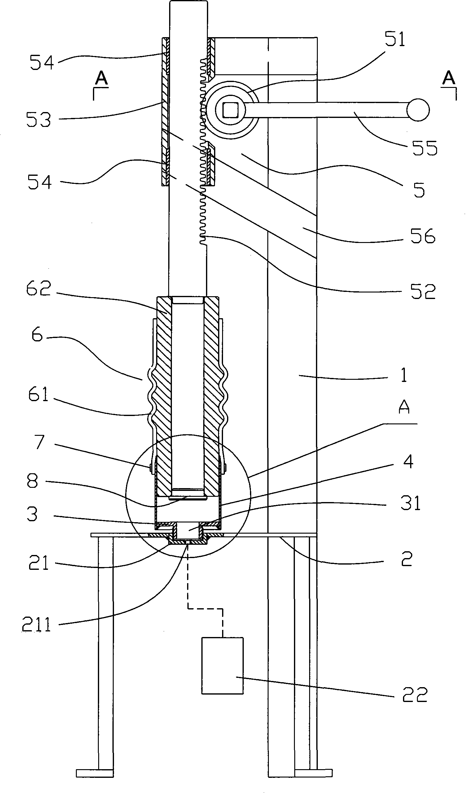

Image

  • A hose depoling method and a device thereof
  • A hose depoling method and a device thereof
  • A hose depoling method and a device thereof

Examples


Embodiment 1

[0023] The high-pressure medium in this embodiment is high-pressure gas.

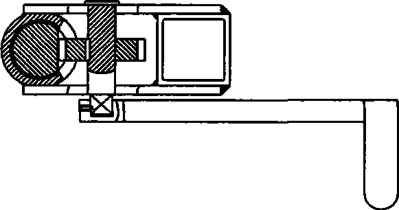
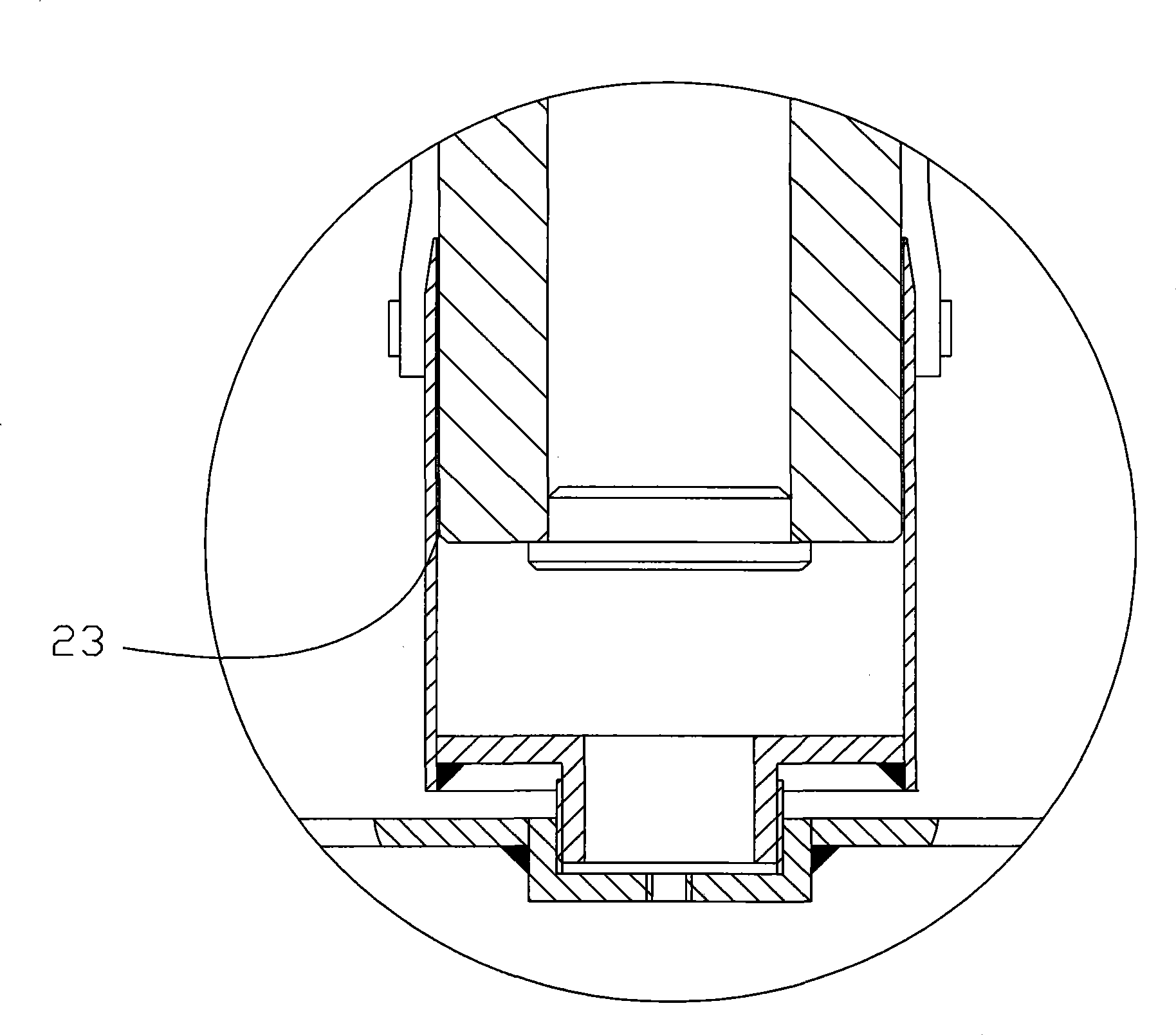
[0024] Such as figure 1 , figure 2 , image 3 As shown, the rubber hose coring device of the present invention includes a support 1 and a high-pressure medium source 22. The lower part of the support 1 is provided with a support base 2, the end surface of the support base is provided with a groove 21, and the middle part of the groove is provided with an air inlet 211. ; The groove 21 is equipped with a chuck 3 that is compatible with it, and the groove 21 and the chuck 3 constitute a support device for a rubber hose with a core, and the support device is used to support the molded rubber hose 6 with a core; The head 3 is airtightly connected with the groove 21 , a central air hole 31 is provided on the chuck 3 , and an annular plug 4 is sealed and connected to the upper end of the chuck 3 . A molding device 5 is arranged above the bracket 1 , a rubber hose with a core 6 is vertically arranged betwe...

Embodiment 2

[0029] The high-pressure medium in this embodiment is high-pressure water.

[0030] Such as Figure 4 , Figure 5 As shown, the rubber hose coring device of the present invention includes a workbench 9 and a water pump 10. The workbench 9 is relatively provided with a support side plate 20 and a protection side plate 21. The support device 11 is horizontally arranged on the support side plate 20, with a mold core The rubber hose is arranged between the supporting side plate 20 and the protecting side plate 21 , and the supporting device 11 and the supporting side plate 20 are fixedly connected by nuts 12 .

[0031] The right end of the support device 11 is sealed and connected with the left end of the ring plug 13, the support device 11 and the ring plug 13 are hollow pipe structures, the left end of the support device 11 is the water inlet, the output end of the water pump 10 is connected to the support device 11 The left end is connected; the right end of the annular plug ...


PUM

PropertyMeasurementUnit
lengthaaaaaaaaaa

Abstract

The invention discloses a hose depoling method, in specific: after a hose model is molded, high-pressure medium is led to the contact surface between a model core and a hose; the high-pressure medium leads the hose to have radial expansion, and the model core is taken out after the hose and the model core mutually separate. A hose depoling device used for applying the method comprises a support device and an annular plug; wherein the support device is used for supporting the hose with the model core; one end of the annular plug is inserted into the contact surface between the model core and the hose; the annular plug can be used for leading the high-pressure medium to the contact surface between the model core and the hose; the high-pressure medium leads the hose to have radial expansion, and the model core is taken out after the hose and the model core mutually separate. By means of the characteristics of high-pressure air or high-pressure water, the method and the device can easily take out the hose with multiple corrugations and long length, thereby solving the problems of difficult depoling and depoling fail of the prior art. Furthermore, the device has the advantages of simple structure, high efficiency and low cost, etc.

Description

technical field [0001] The invention relates to the field of rubber hoses for automobiles, in particular to a method and a device for removing cores from rubber hoses. Background technique [0002] With the development of the automobile industry, rubber hoses of various calibers are installed on the air inlet and outlet systems of automobiles. When making such multi-corrugated, large-length, corrugated and long-length rubber hoses, it is extremely difficult for the forming core to come out. Traditional core removal generally adopts the following two methods: one is to make the corrugated section in the multi-corrugated core into a split structure, and withdraw the corrugated section separately during core removal to complete the core removal. The second is to make the large-length rubber hose into a two-section or multi-section structure, and then connect the steel pipe or plastic pipe through interpolation, and add clamps to fix and connect the multi-section rubber hose. ...

Claims


Application Information

Patent Timeline
Patent Type & Authority Applications(China)
IPC IPC(8): B29C33/44B29C33/46
Inventor 李警矫水田矫滨田赵艳高忠军于晓国陈雪江李思全温源
Owner 北京腾龙天元橡塑有限公司
Learn More