

Suppressing circuit of power-on impact current
A technology for suppressing circuit and electric shock, applied in emergency protection circuit devices, circuit devices, emergency protection circuit devices for limiting overcurrent/overvoltage, etc., can solve the problems of power-on inrush current, etc. inhibiting effect
- Summary
- Abstract
- Description
- Claims
- Application Information
AI Technical Summary
Problems solved by technology
Method used
Image

Examples
specific Embodiment approach 1
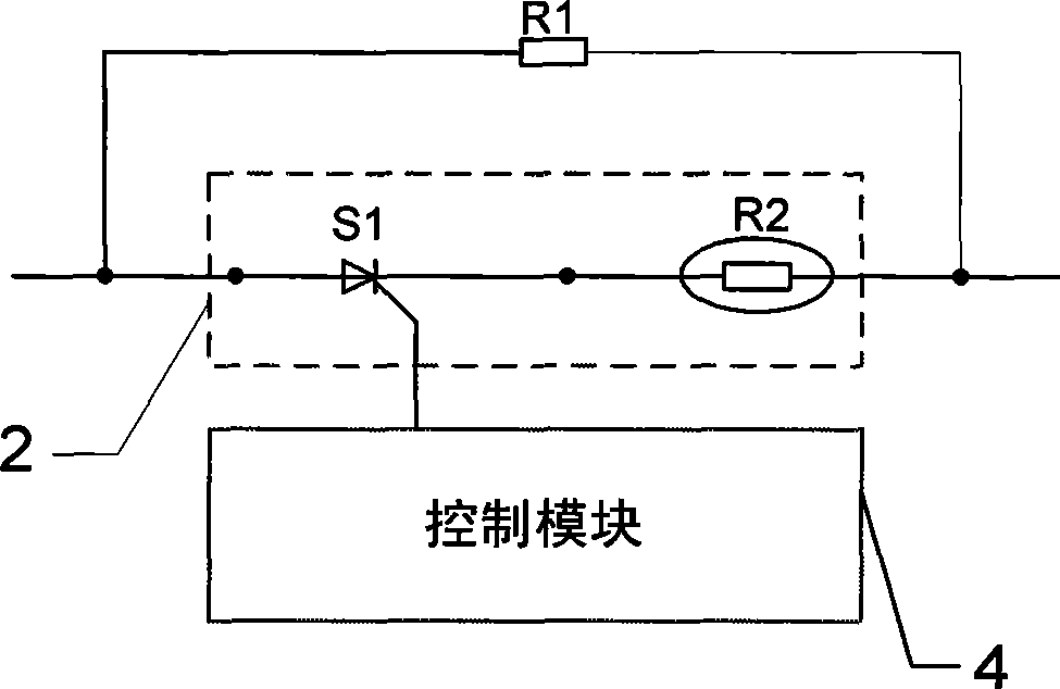
[0007] Specific implementation mode one: combine figure 1 Describe this specific embodiment, a suppression circuit for power-on surge current, which includes a first current-limiting resistor R1, a second current-limiting circuit 2 and a control module 4, and the second current-limiting circuit 2 includes a thyristor S1 and The second current-limiting thermistor R2, the cathode of the thyristor S1 is connected to one end of the second current-limiting thermistor R2, the second current-limiting circuit 2 is connected in parallel with the first current-limiting resistor R1, the The control signal output terminal of the control module 4 is connected with the control terminal of the thyristor S1.
[0008] The first current limiting resistor R1 of the present invention is used to realize the slow rise of the input current; the second current limiting circuit 2 is used to realize the input current suppression and smooth startup of the converter 11 during operation; the control modul...
specific Embodiment approach 2
[0009] Embodiment 2: The difference between this embodiment and the power-on inrush current suppression circuit described in Embodiment 1 is that the thyristor S1 is a one-way thyristor.
[0010] In this specific embodiment, the power supply voltage is a DC voltage.
specific Embodiment approach 3
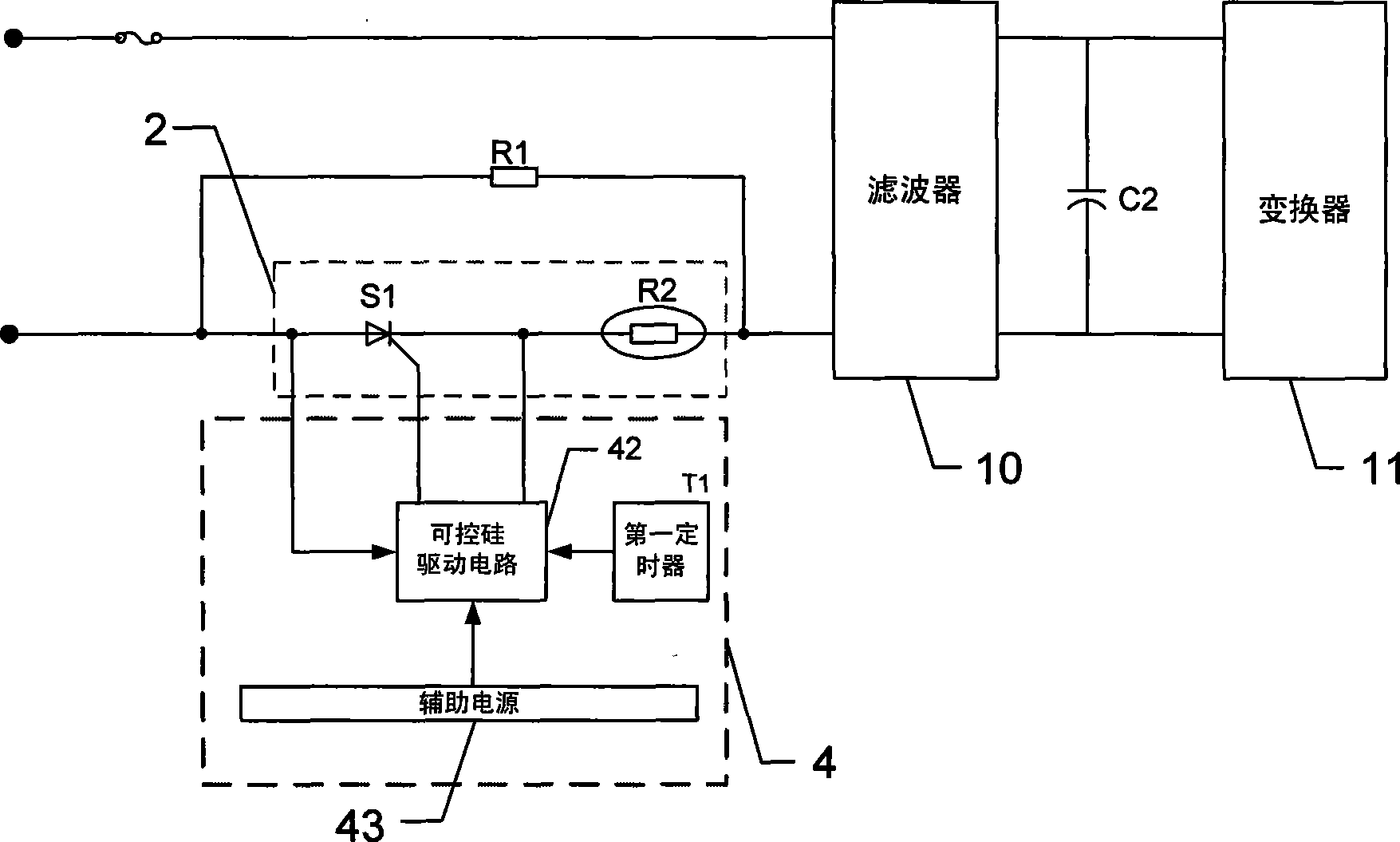
[0011] Specific implementation mode three: combination figure 2 This specific embodiment is described. The difference between this specific embodiment and the power-on inrush current suppression circuit described in the second specific embodiment is that the control module 4 includes a thyristor drive circuit 42 and a first timer T1. The thyristor control signal output end of the thyristor drive circuit 42 is connected to the control end of the thyristor S1 , and the control signal output end of the first timer T1 is connected to the control signal input end of the thyristor drive circuit 42 . The power input end of the thyristor drive circuit 42 is connected to the anode of the thyristor S1. The suppression circuit charges the output capacitor C2 through the filter 10, and outputs it through the converter 11 after the charging is completed.
[0012] Working principle: The circuit of the present invention uses the first current-limiting resistor R1, whose function is to limi...
PUM
 Abstract
Description
Claims
Application Information