Eureka AIR delivers breakthrough ideas for toughest innovation challenges, trusted by R&D personnel around the world.

Power-on impulse current suppression circuit of airborne display

A technology of current suppression and suppression circuits, which is applied in the direction of emergency protection circuit devices, circuit devices, emergency protection circuit devices, etc. for limiting overcurrent/overvoltage, and can solve circuit work uncertainty, large surge current, switching To avoid problems such as electric shock damage, to improve reliability and stability, and to suppress the impact current of power-on

Pending Publication Date: 2021-03-26
SUZHOU CHANGFENG AVIATION ELECTRONICS
View PDF0 Cites 0 Cited by
  • Summary
  • Abstract
  • Description
  • Claims
  • Application Information

AI Technical Summary

Problems solved by technology

At present, there is no very effective method to solve the problem of suppressing the power-on surge current: traditional series fixed resistors, thermistors and other methods have defects, for example, they cannot solve the contradiction between suppressing the peak value of the current and the normal steady-state value , can not solve the problem of excessive power dissipation of the current-limiting resistor and excessive voltage drop of the current-limiting resistor during steady-state operation: in particular, it cannot accurately suppress the peak value of the surge current, making the circuit work uncertain
Another traditional method is to use resistance current limiting and time-delay short-circuit resistance. This method cannot judge the charging state of the subsequent load capacitor. Simply forcing the short-circuit resistance after a delay may still cause a large surge current and cause It will cause damage to the electric shock of the switch, and it cannot adapt to capacitive loads of different sizes and capacities

Method used


Image

  • Power-on impulse current suppression circuit of airborne display
  • Power-on impulse current suppression circuit of airborne display

Examples


Embodiment Construction

[0017] Embodiments of the present disclosure will be described in detail below in conjunction with the accompanying drawings.

[0018] Embodiments of the present disclosure are described below through specific examples, and those skilled in the art can easily understand other advantages and effects of the present disclosure from the contents disclosed in this specification. Apparently, the described embodiments are only some of the embodiments of the present disclosure, not all of them. The present disclosure can also be implemented or applied through different specific implementation modes, and various modifications or changes can be made to the details in this specification based on different viewpoints and applications without departing from the spirit of the present disclosure. It should be noted that, in the case of no conflict, the following embodiments and features in the embodiments can be combined with each other. Based on the embodiments in the present disclosure, a...


PUM


Abstract

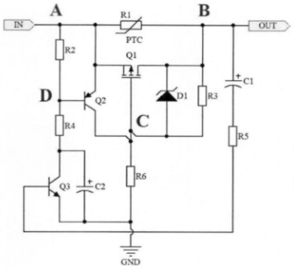
The embodiment of the invention provides a power-on impulse current suppression circuit of an airborne display. The circuit comprises a first thermistor (R1), a first P-channel MOSFET (Q1), a first PNP transistor (Q2), a second NPN transistor (Q3), a first capacitor (C1), a second capacitor (C2), a first resistor (R2), a second resistor (R3), a third resistor (R4), a fourth resistor (R5), and a fifth resistor (R6). The circuit provided by the invention can be suitable for all avionics equipment, and the circuit is connected in series between a power supply input and a filter capacitor / energy storage capacitor, so that the power-on impact current can be effectively suppressed, and the reliability and stability of the avionics equipment are improved.

Description

technical field [0001] The present disclosure relates to the technical field of avionics equipment, in particular to a power-on surge current suppression circuit for an airborne display. Background technique [0002] In the field of avionics, avionics equipment draws power from the aircraft power system. For the aircraft power system, it is an electrical device. Most avionics equipment is designed with a filter circuit. Generally, a large-capacity capacitor or energy storage is designed at the power input end. capacitance. At present, all airborne displays have a power-down hold function, so there will be a large internal energy storage capacitor during product design to meet the power-down hold function of the display. Since the voltage of the capacitor at the front end of power-on is zero, the impedance of the power input circuit Low, the capacitor is charged at the moment of power-on, the charging current is very large, and a large surge current is generated. Excessive ...

Claims


Application Information

Patent Timeline
Patent Type & Authority Applications(China)
IPC IPC(8): H02H9/02
CPCH02H9/026
Inventor 卢小军段士龙杨粤涛张传森于杰高伟松
Owner SUZHOU CHANGFENG AVIATION ELECTRONICS
Why Eureka
Eureka Blog
Learn More