Method and device for discharging liquid material

A liquid material and discharge device technology, which is applied in the direction of the device and coating of liquid coating on the surface, can solve the problem of uneven liquid material volume and achieve the effect of preventing uneven discharge

Active Publication Date: 2009-09-16
MUSASHI ENG INC
View PDF2 Cites 1 Cited by
  • Summary
  • Abstract
  • Description
  • Claims
  • Application Information

AI Technical Summary

Problems solved by technology

[0005] It is known that when there are air bubbles in the flow path of the discharge device of this structure, the amount of liquid material discharged by the device is uneven.

Method used


Image

  • Method and device for discharging liquid material
  • Method and device for discharging liquid material
  • Method and device for discharging liquid material

Examples


Embodiment 1

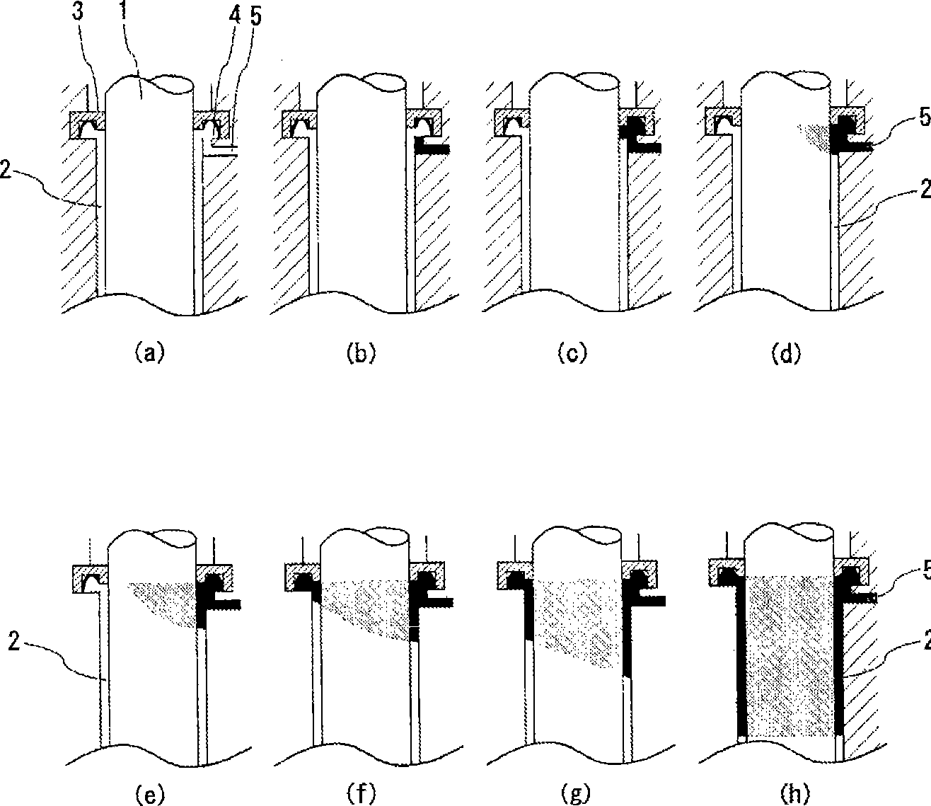
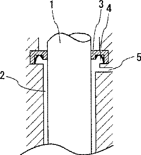
[0113] Figure 4 The disclosed device of this embodiment relates to a discharge device in which a liquid material is scattered and discharged using a nozzle 7 . More specifically, the device of this embodiment is a liquid material discharge device in which the liquid material is scattered and discharged from the tip of the nozzle 7 by the high-speed axial movement of the working shaft and the subsequent sudden stop.

[0114] structure

[0115] The main components of the device of this embodiment are: the flow path block 16 with the nozzle 7 inserted, the connection block 17 connecting the flow path block 16 and the air pressure block 18, and the structure that makes the working shaft 1 move. The driving source is the pneumatic block 18 and the working shaft 1 that reciprocates in the space provided inside each block.

[0116] The working shaft 1 is composed of a rod-shaped body shaft portion 21 and a flange 20 affixed to the rear end of the shaft body portion 21 . The worki...

Embodiment 2

[0136] The device of this embodiment is an example suitable for use as a valve for liquid material discharge.

[0137] Figure 8 The device of the present embodiment shown is that the liquid material that is introduced into the valve and has been adjusted to a required pressure is discharged from the nozzle 7 while the working shaft 1 is separated from the valve seat 6, and the working shaft 1 is a discharge device that matches the valve seat 6 and stops the discharge from the nozzle 7.

[0138] structure

[0139] The device of this embodiment has a structure in which the pneumatic block 18 and the channel block 16 are directly connected without the connection block 17 .

[0140] The working shaft 1 having a rod-shaped shaft portion 21 and a flange 20 formed at the rear end of the shaft portion 21 is configured to extend between the blocks.

[0141] The flange 20 of the working shaft 1 is configured to be in close contact with the inner wall surface of the chamber 12 formed...

Embodiment 3

[0162] Figure 9 The disclosed device of this embodiment relates to a discharge device in which a liquid material is discharged from a nozzle 7 by rotating a working shaft 1 having a spiral flange at its tip.

[0163] structure

[0164] The main constituent elements of the device of this embodiment are a base plate 24, a top plate 25 provided at its upper end, a motor 50 provided at its upper end, a sealing block 23 provided at the center of the base plate 24, a bottom plate 24 lower end and It is connected to the flow channel block 16 arranged in the sealing block 23 and the working shaft 1 that rotates in the space provided inside each block.

[0165] The working shaft 1 is composed of a shaft body 21 and a front end 22 with a helical flange extending toward the shaft body 21 , and is arranged to pass through the sealing block 23 and extend toward the flow path block 16 . The shaft part 21 is connected to the rotating shaft of the motor 50 inserted through the through hole...


PUM


Abstract

A method and device for discharging a liquid material, which can, in filling a flow path with a liquid material when operation of the device is started, fill the flow path with the liquid material without residual gas or gas bubbles. In the method and device, a working shaft is inserted through a first flow path, which is a circular hole communicating with a nozzle, the liquid material is placed from a second flow path, which communicates with the first flow path, to fill the first flow path with the liquid material, and thereby the liquid material is discharged. A space (4) connected to the first flow path and second flow path is provided above the first flow path. Flow resistance of the liquid material flowing from the second flow path into the first flow path is made greater than that of the liquid material flowing from the second flow path into the space (4). By this gas, bubbles are prevented from remaining in the device.

Description

technical field [0001] The present invention relates to a liquid material discharging method and device for discharging the liquid material from a discharge port, and more specifically, to a method and device capable of discharging the liquid material without residual gas when filling the liquid material in a flow path communicating with the discharge port. Discharge method and device for filled liquid material. [0002] In addition, the so-called "discharging" in the present invention includes: a discharge method in which the liquid material contacts the workpiece before leaving the nozzle, and a discharge method in which the liquid material contacts the workpiece after leaving the nozzle. Background technique [0003] A device for discharging a liquid material is known in which a shaft body that rotates or moves forward and backward is arranged in a flow path from a supply port for supplying the liquid material to a discharge port for discharging the liquid material, and t...

Claims


Application Information

Patent Timeline
Patent Type & Authority Applications(China)
IPC IPC(8): B05D1/26B05C5/00
CPCB05C5/0237B05C5/0225B05C5/00B05D1/26
Inventor 生岛和正
Owner MUSASHI ENG INC
Why Eureka
Try Eureka