Water-shedding indoor wall mounted cabinet

a wall mounted cabinet and water-shedding technology, which is applied in the direction of electrical equipment casings/cabinets/drawers, substation/switching arrangement casings, casings/cabinets/drawers details, etc., can solve the problems of denying access to the general workforce, electrical shorts and/or other equipment failures, and unable to meet the needs of the general workforce, so as to prevent water ingress and heat egress

a wall mounted cabinet and water-shedding technology, which is applied in the direction of electrical equipment casings/cabinets/drawers, substation/switching arrangement casings, casings/cabinets/drawers details, etc., can solve the problems of denying access to the general workforce, electrical shorts and/or other equipment failures, and unable to meet the needs of the general workforce, so as to prevent water ingress and heat egress

US20050017610A1Inactive Publication Date: 2005-01-27FUJITSU LTD

Image

  • Water-shedding indoor wall mounted cabinet
  • Water-shedding indoor wall mounted cabinet
  • Water-shedding indoor wall mounted cabinet

Examples


Embodiment Construction

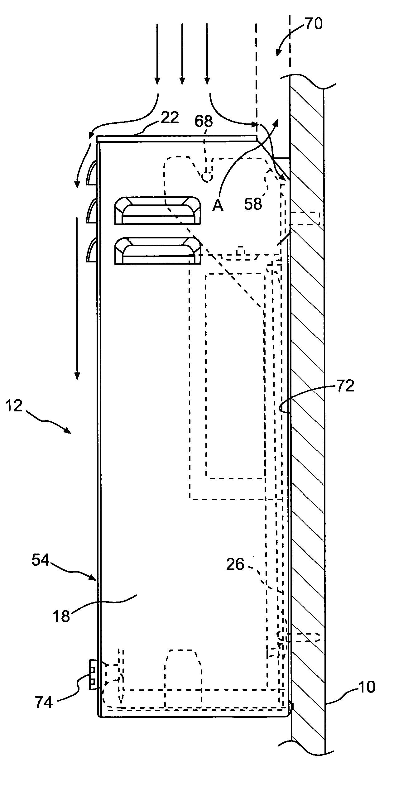
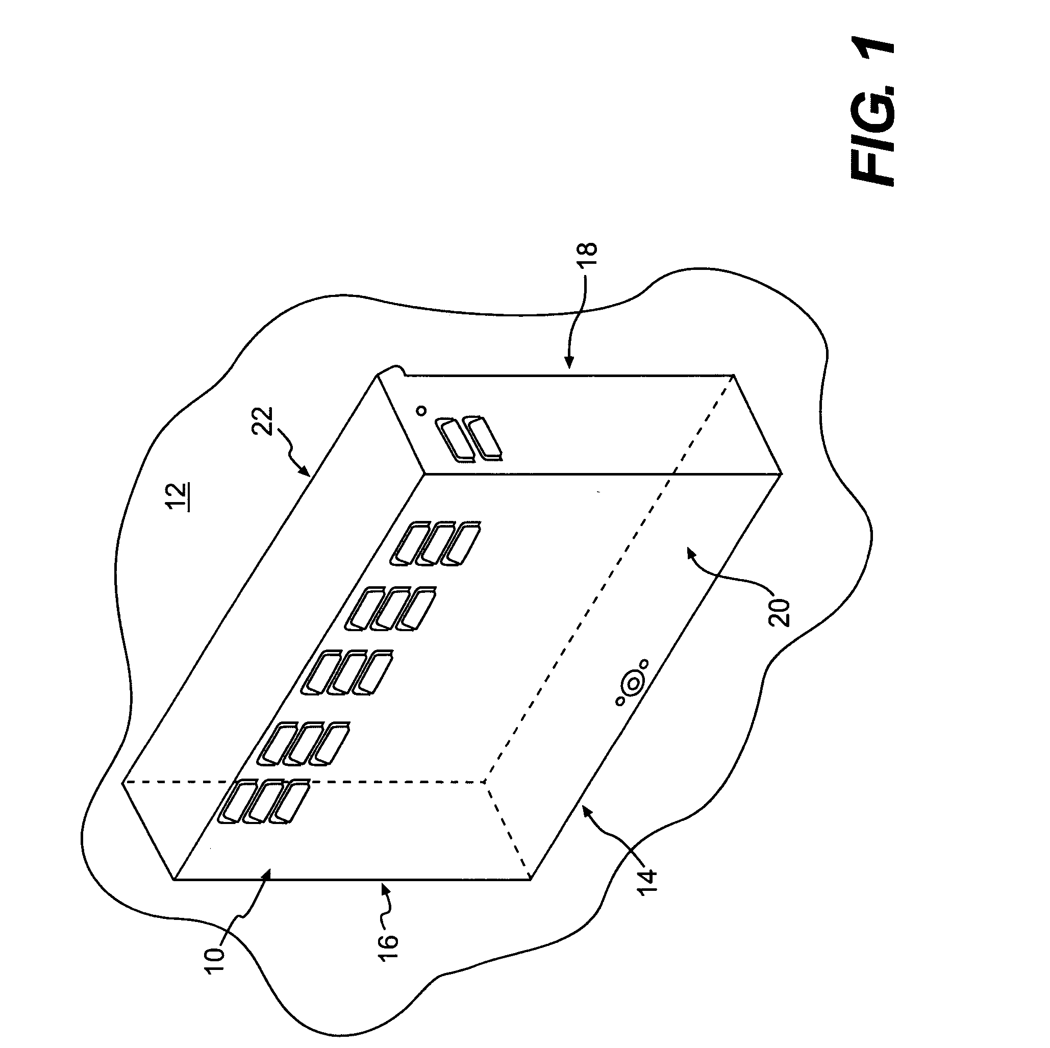
[0021] Referring to FIG. 1, a wall mounted cabinet 10 is mounted on a wall 12. The wall 12 is preferably an interior wall within a room that is may be designated as an equipment room to contain electrical, telecommunications, and / or computer equipment. While the cabinet 10 is preferably located in such a room, it is also possible that the cabinet is mounted on a wall of other interior spaces that are less confined and perhaps designated for multiple uses. It is also possible that the cabinet could be located on a wall that is semi-enclosed but covered. Thus, the term “interior” could encompass building structures that are not confined by four walls, a ceiling and a floor. The term “interior” denotes a space that is not directly exposed to the elements, although the preferred location of the cabinet 10 is in an interior space defined in the traditional sense.

[0022] Moreover, the cabinet 10 of the present invention is intended to be mounted on a vertical wall, rather than horizontal ...


PUM


Abstract

A wall-mounted cabinet has two components. The first, a back portion, is fixedly connected to a wall, and the second, a cover portion, is pivotally and detachably connected to the second. A vent is formed in the top of the cover portion, but in a manner that does not permit water to enter but does permit heated air generated from with the cabinet to exit. In order to accomplish this, a water-diverting plate is provided on the back portion. The plate is oriented to extend across the width of the vent at an angle, so that water entering the vent is directed towards a gap formed between the wall and the outer surface of the back portion.

Description

BACKGROUND OF THE INVENTION [0001] The present invention relates generally to indoor wall mounted cabinets, and more particularly, to cabinets that have ventilation and water shedding features. Such features are particularly appropriate for use in housing sensitive electrical and / or electro-mechanical components, such as those frequently found in the telecommunications field. DESCRIPTION OF THE RELATED ART [0002] In many office buildings today it is common for a business entity to have a room where sensitive network hardware, computers, telephone lines and switches are located. These rooms are usually windowless and located in less desirable locations of a floor plan. They can also contain fuse or breaker boxes and transformers providing electrical service to the building, floor of the building, or portion of a floor. Such rooms are generally kept locked to thus deny access to the general workforce. [0003] For rooms which contain principally or exclusively telecommunications equipme...

Claims


Application Information

Patent Timeline
27 Jan 2005
Publication
US20050017610A1
IPC
A47F5/08; H02B1/28; H02B1/40; H04Q1/02; H05K5/02
CPC
H02B1/28; H02B1/40; H04Q2201/06; H04Q1/021; H05K5/0213; H04Q1/035; H04Q1/114; H04Q2201/08
Inventors
MISTRY, MAHESH BALU; ROCCOBERTON, TODD