Method and device for error management

A fault management and faulty technology, applied in general control system, generation of response errors, instruments, etc., can solve problems that hinder the processing of system customer projects, achieve the effect of reducing fault sensitivity, reducing overhead, and simplifying analysis

Inactive Publication Date: 2009-09-16
ROBERT BOSCH GMBH
View PDF2 Cites 10 Cited by
  • Summary
  • Abstract
  • Description
  • Claims
  • Application Information

AI Technical Summary

Problems solved by technology

[0008] This distribution of tasks and responsibilities significantly hampers the product configuration of said systems and the processing of customer projects
Apart from this, it is not possible in conventional systems to use tools for automated documentation within the three areas mentioned, namely detection of resulting states, avoidance of subsequent failures and handling of multiple failures

Method used


Image

  • Method and device for error management
  • Method and device for error management

Examples


Embodiment Construction

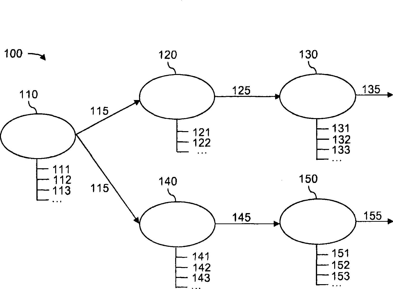
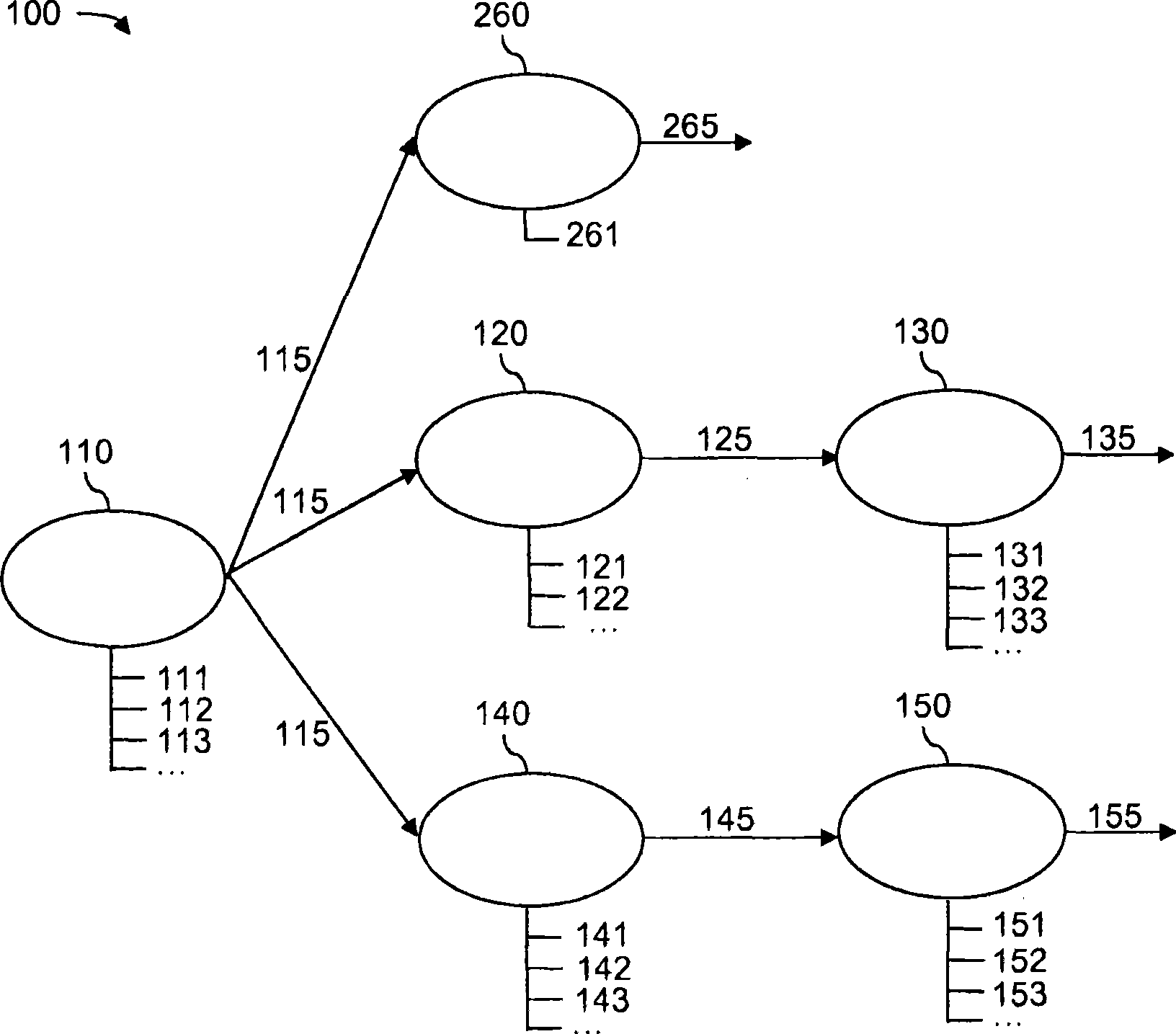
[0035] The method according to the invention and the device according to the invention can be represented in the form of diagrams. The relationship diagram here depicts a system with multiple components. The relationship diagram contains all monitored components of the system. All monitored components are on the one hand all hardware components of the system and on the other hand the signals provided by the hardware components. The monitored components are shown as nodes in the relationship diagram. The relationships between the components are shown in the relationship graph by the connections between the nodes.

[0036] The relationship graph is directional and acyclic. "Directed" means that a connection between two nodes of the relationship graph is always passed in only one direction. If any connection is followed starting from any of the nodes, neither returns to the starting node nor passes through one of the other nodes more than once. The relationship graph is ther...


PUM


Abstract

A method for error management in a system (100) having a plurality of components (110, 120), wherein error states of the components can be displayed by means of status values (115, 125), is characterized in that a first status value (115) is determined as a function of an error state of a first component (110) and a second status value (125) is determined as a function of an error state of a second component (120) and as a function of the first status value (115).

Description

technical field [0001] The invention relates to a method for fault management according to the preamble of claim 1 , a corresponding device according to the preamble of claim 12 as well as a corresponding computer program and a computer program product . Background technique [0002] DE 197 31 116 A1 deals with a controller for a system. The system is provided with sensors. The measured values ​​of the sensor can be transmitted to the control unit via the connecting line. The control system thus receives information about the state of the system. [0003] DE 103 02 054 A1 concerns the inspection of components of internal combustion engines. A diagnostic function is assigned to each component, which correspondingly communicates with the central functions via the interface. [0004] In the following, reference is made primarily to electronic stability programs, which can be used, for example, in the automotive sector. However, the method or the device is not restricted t...

Claims


Application Information

Patent Timeline
Patent Type & Authority Applications(China)
IPC IPC(8): G06F11/07
CPCG05B23/0267B60W50/04F02D41/22G05B2219/24093
Inventor P·沃尔茨M·比林格A·谢弗
Owner ROBERT BOSCH GMBH
Why Eureka
Try Eureka