Method and apparatus for robot calibrations with a calibrating device

A technology for calibrating devices and manipulators, applied in manipulators, using optical devices, program-controlled manipulators, etc., can solve the problems of time, cost complexity and cost

Inactive Publication Date: 2009-09-23
APPLIED MATERIALS INC
View PDF1 Cites 35 Cited by
  • Summary
  • Abstract
  • Description
  • Claims
  • Application Information

AI Technical Summary

Problems solved by technology

Photographic techniques must be taught to perform manipulator calibration to align targets of various types found in manufacturing equipment, creating additional complexity and expense in terms of time, cost, operation and / or maintenance sources

Method used


Image

  • Method and apparatus for robot calibrations with a calibrating device
  • Method and apparatus for robot calibrations with a calibrating device
  • Method and apparatus for robot calibrations with a calibrating device

Examples


Embodiment Construction

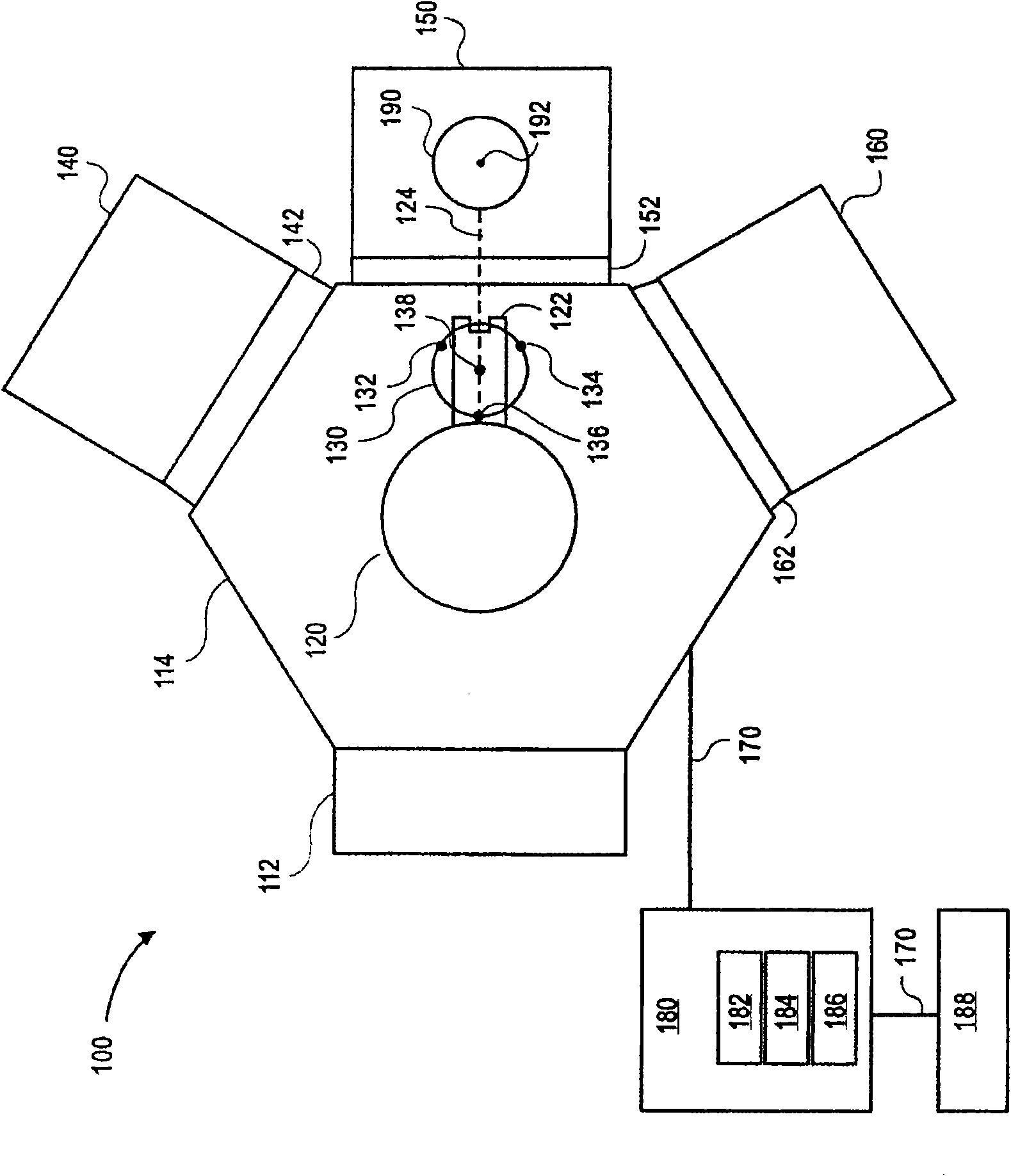
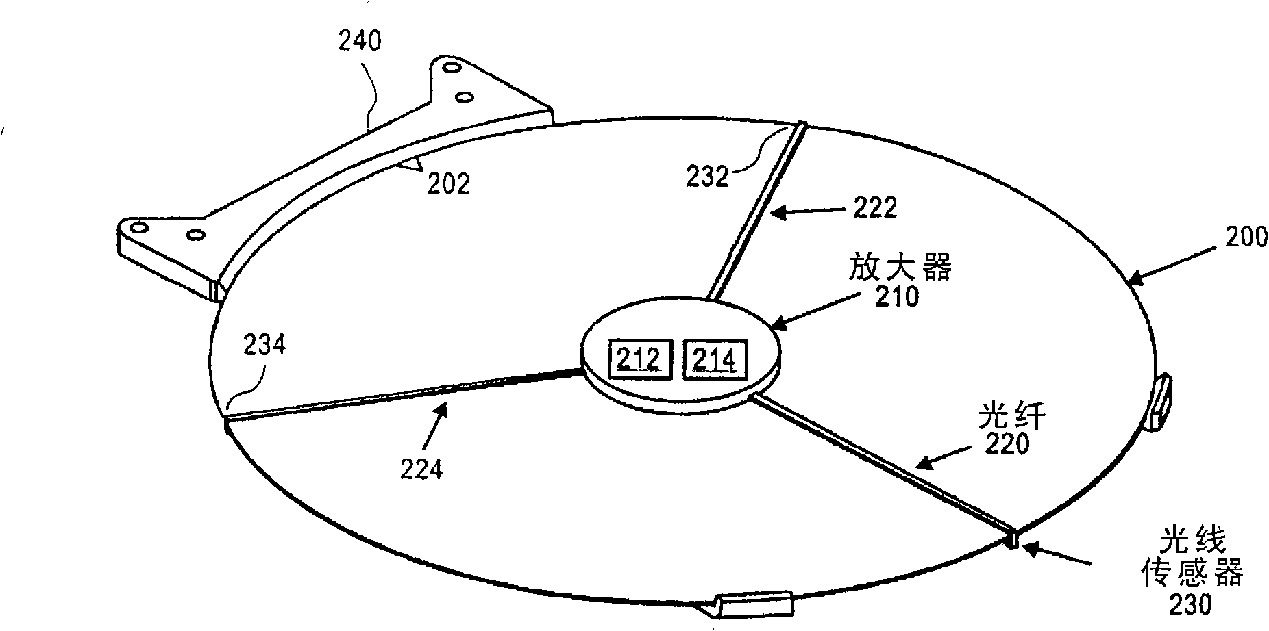
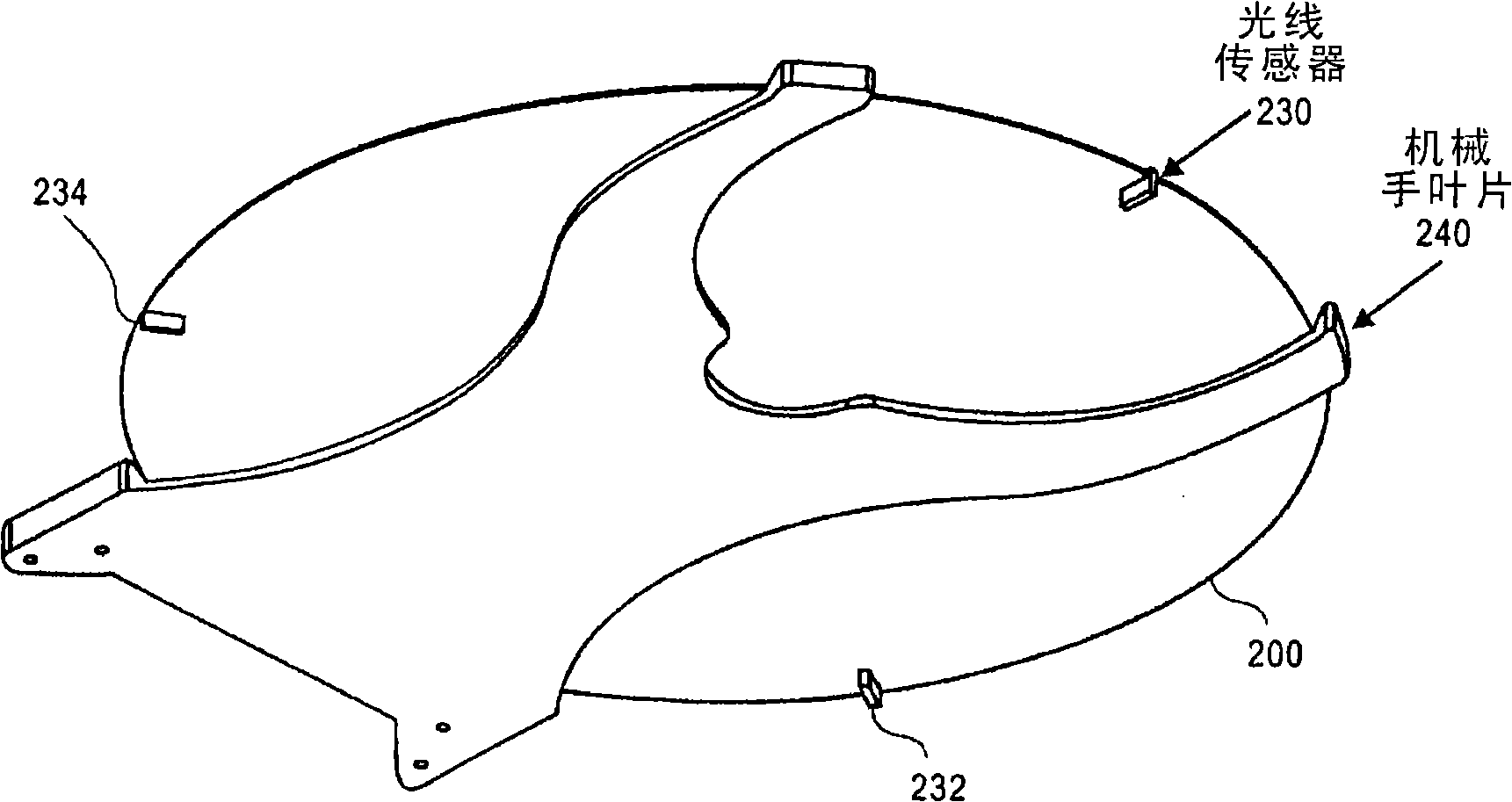
[0030] Described herein are methods and apparatus for performing calibration of manipulator elements. In one embodiment, a method for performing a manipulator calibration includes sensing a start point and an end point of a target with sensors positioned on a calibration device. The method further includes calculating a center of the object based on the start point and the end point of the object. The method further includes determining an offset between the center of the target and the manipulator blade positioned at the reference position. The method further includes calibrating the manipulator position based on the offset.

[0031] In another embodiment, a method for performing robot calibration includes moving a calibration device across a target (eg, a wafer chuck). The method then includes using a sensor positioned on the calibration device to measure the distance between a spot of light from the sensor and the perimeter of the target. Next, the method includes determ...


PUM


Abstract

Described herein is a method and apparatus for performing calibrations on robotic components. In one embodiment, a method for performing robotic calibrations includes moving the calibrating device across a target (e.g., a wafer chuck). Next, the method includes measuring distances between light spots from the sensors and a perimeter of the target using the sensors located on the calibrating device. Next, the method includes determining a displacement of the calibrating device relative to a center of the target. Then, the method includes determining a rotation angle of the calibrating device relative to a system of coordinates of the target. Next, the method includes calibrating a robot position of the robot based on the displacement and rotation angle of the calibrating device with respect to the target.

Description

[0001] related application [0002] This application claims priority to US Provisional Patent Application No. 60 / 969,123, filed August 30, 2007, and entitled "METHOD ANDAPPARATUS FOR ROBOT CALIBRATIONS WITH CALIBRATING DEVICE," which is hereby incorporated by reference. technical field [0003] Embodiments of the present invention relate to manipulator calibration, and more particularly to utilizing a sensed calibration device for manipulator calibration. Background technique [0004] Many industries use sophisticated manufacturing equipment that includes multiple sensors, controls, and robotic elements, each of which can be carefully monitored during the process to ensure product quality. The robotic elements require calibration to precisely define the preset positions of the mechanical structures of the robotic system in order to properly ensure the system functionality. By calibrating the mechanical mechanism of the manipulator, proper transfer of objects can be establi...

Claims


Application Information

Patent Timeline
Patent Type & Authority Applications(China)
IPC IPC(8): B25J9/16H01L21/68H01L21/00H01L21/677
CPCH01L21/67748H01L21/67742G05B2219/37608G01B11/03G05B2219/39047G01B21/042G05B2219/39056H01L21/681B25J9/1692G05B2219/37278H01L21/68
Inventor 维杰依·撒卡利赛卡尔·克里斯娜萨米莫德凯·赖斯卡唐纳德·佛丹纳尔里奈特·史姆什马文·L·弗里曼杰弗里·C·哈德更斯
Owner APPLIED MATERIALS INC
Why Eureka
Try Eureka