Vision system

a vision system and system technology, applied in the field of vision systems, can solve the problems of unscheduled system maintenance, unsuitable costly damage or/and other problems, to achieve the effect of avoiding the use of human labor in such locations, saving system maintenance costs, and saving maintenance costs

Active Publication Date: 2006-08-01
APPLIED MATERIALS INC
View PDF70 Cites 41 Cited by
  • Summary
  • Abstract
  • Description
  • Claims
  • Application Information

AI Technical Summary

Problems solved by technology

Moreover, robots can be used in locations where the proximity to moving components or sensitive environments makes the use of human labor in such locations undesirable.
This is particularly important in semiconductor processing systems where misplaced or out-of-position substrates result in costly damage or / and unscheduled system maintenance.
Misaligned substrates are often damaged, damage other substrates or equipment, or are poorly processed due to misalignment and may be discarded.
If the substrates contact one another, one or both of the substrates may become damaged.
If retrieval of the dislodged substrate requires accessing interior portions of the system operating under vacuum, hours of production time will be lost for decontamination and reestablishment of a vacuum environment within the effected chambers.
This undesirably places the operator in a position exposed to the range of motion of the robot were personal injury or system damage may occur.
Moreover, lengthy pump-downs must be performed to return the system to operation pressures.
During periods where the system is shut down, no wafers are processed and valuable production time is lost.
This all results in undesirable loss of production capacity that must be repeated wherever recalibration is needed.

Method used


Image

  • Vision system
  • Vision system
  • Vision system

Examples


Embodiment Construction

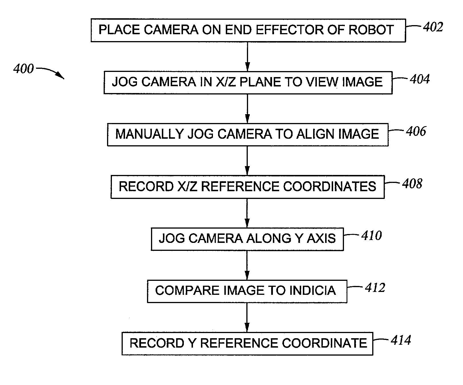
[0029]The present invention generally provides a vision system for capturing images within in a semiconductor processing system and related equipment. The images may be used to calibrate a position of a robot's end effector and for system inspection. The invention is illustratively described below with reference to determining the position of a robot's end effector within a semiconductor processing system or cluster tool. However, it should be understood that the invention may be utilized to perform a variety of inspection and / or calibration functions within a semiconductor processing system without having to open the system to the ambient (i.e., surrounding) environment. Moreover, the invention has utility in other semiconductor processing system configurations, such as chemical mechanical polishing systems, electrochemical deposition and polishing systems, where images acquired from a mobile camera are desired.

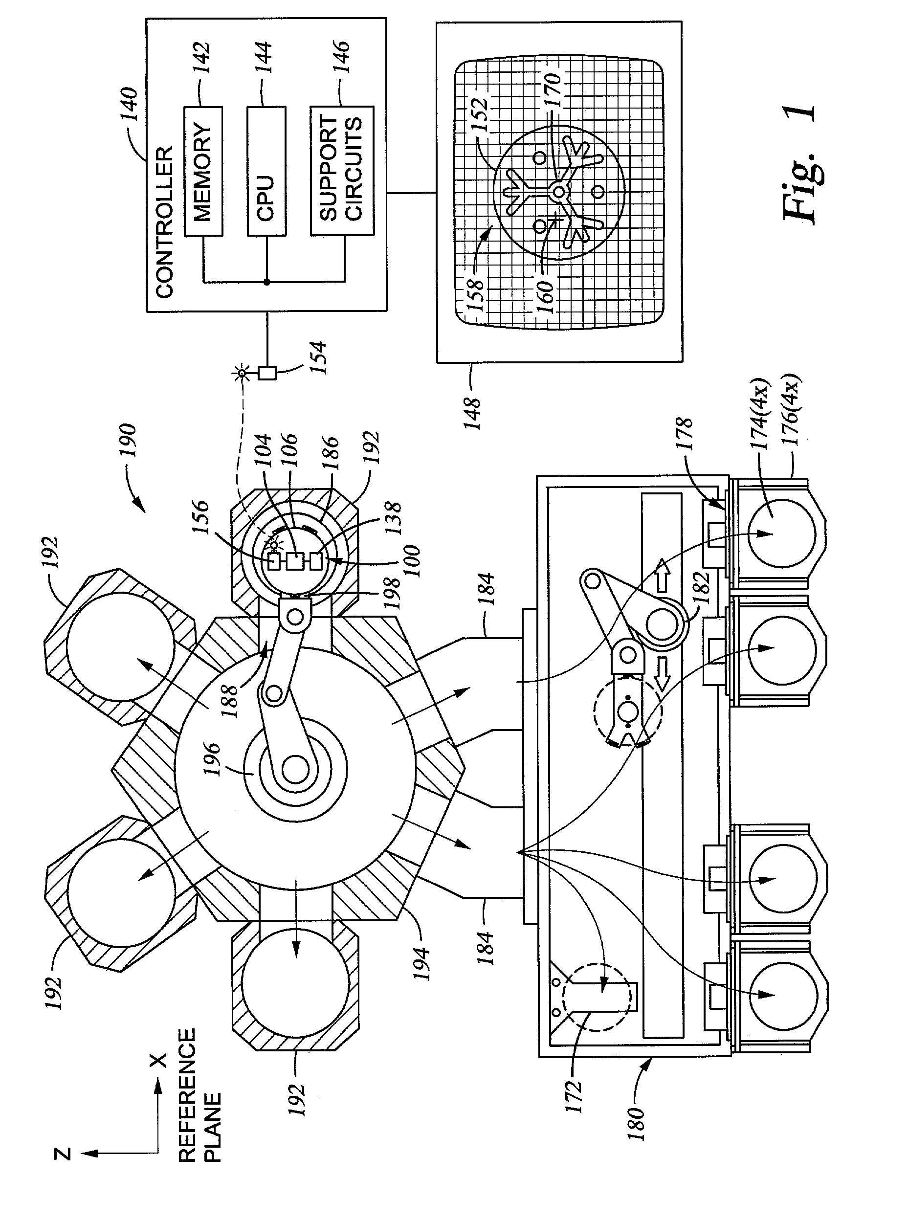
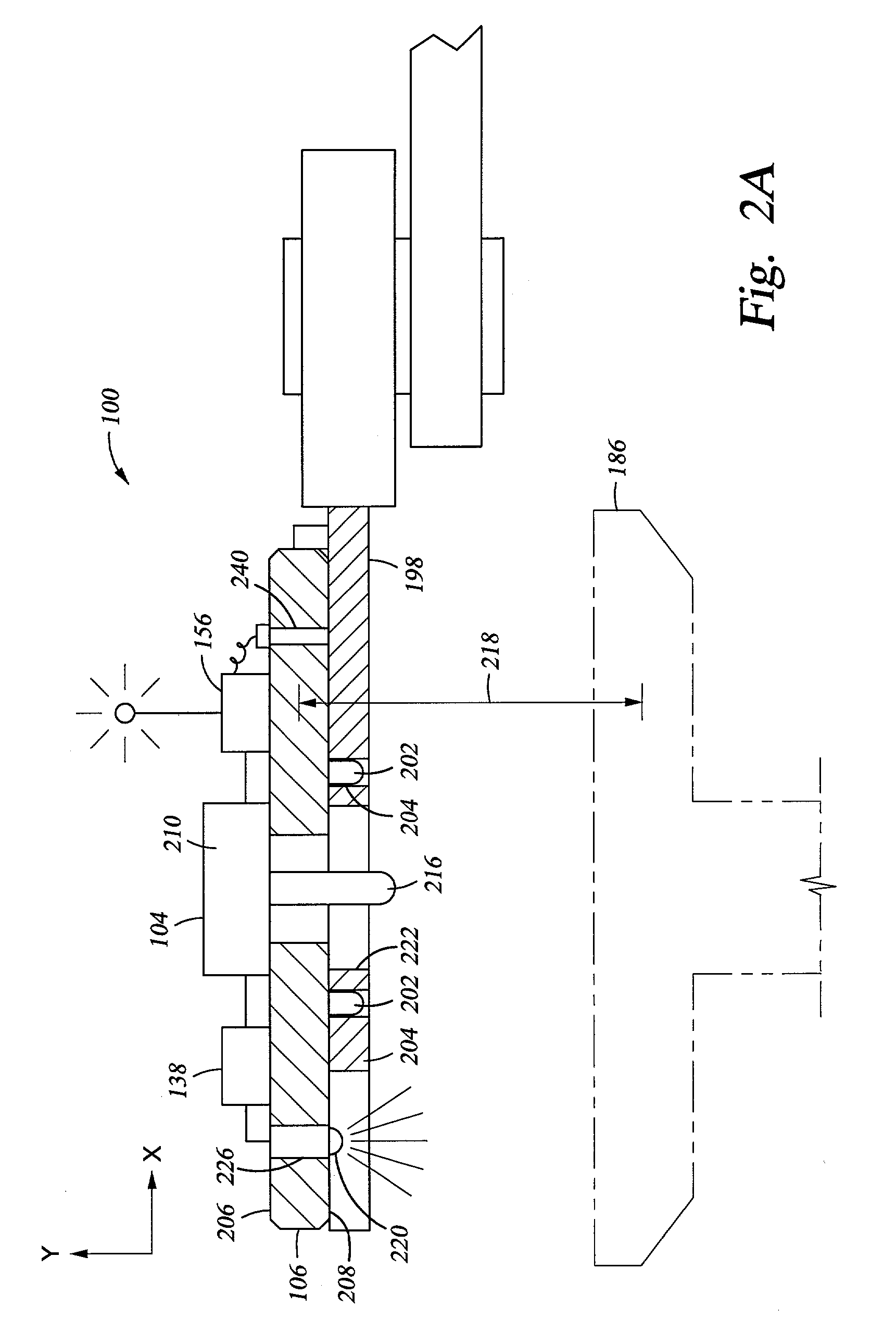
[0030]FIG. 1 depicts one embodiment of an exemplary processing system 1...


PUM


Abstract

Generally a method and apparatus for viewing images within a processing system is provided. In one embodiment, an apparatus includes a plate having a camera, transmitter and battery coupled thereto. The plate is adapted to be transported about a semiconductor processing system by a substrate transfer robot thereby allowing images within the system to be viewed remotely from the system. The viewed images may be used for system inspection and calibration of robot position, among other uses.

Description

BACKGROUND OF THE DISCLOSURE[0001]1. Field of the Invention[0002]Embodiments of the present invention relate generally to a vision system, a method for inspecting a processing system and a method for determining the position of an object within a processing system.[0003]2. Background of the Invention[0004]The use of robots in automated processing systems has become increasingly popular. Robots can often perform repeated tasks with the precision and efficiency generally not achievable through the use of human labor. Moreover, robots can be used in locations where the proximity to moving components or sensitive environments makes the use of human labor in such locations undesirable.[0005]This is particularly important in semiconductor processing systems where misplaced or out-of-position substrates result in costly damage or / and unscheduled system maintenance. Misaligned substrates are often damaged, damage other substrates or equipment, or are poorly processed due to misalignment and...

Claims


Application Information

Patent Timeline
Patent Type & Authority Patents(United States)
IPC IPC(8): G06F19/00B25J9/22B25J9/16B25J13/08H01L21/00H01L21/02H01L21/68
CPCB25J9/1697H01L21/681H01L21/67259H01L21/00H01L21/02
Inventor SADIGHI, IRAJHUDGENS, JEFFRICE, MICHAELWYKA, GARY
Owner APPLIED MATERIALS INC
Why Eureka
Try Eureka