Autonomous global relocation method for robots and robot

A robot and relocation technology, applied in the field of artificial intelligence navigation, can solve the problems of high production cost and R&D cost, achieve the effect of accelerating the convergence speed and solving the kidnapping problem

Inactive Publication Date: 2018-04-13
BENEWAKE BEIJING TECH CO LTD
View PDF8 Cites 38 Cited by
  • Summary
  • Abstract
  • Description
  • Claims
  • Application Information

AI Technical Summary

Problems solved by technology

The commonly used global relocation technology is mostly vision-based relocation technology. This technology has high calculation accuracy, but it is restricted by hardware equipment and image processing technology. The hardware needs to meet the rapid acquisition and calculation of images, that is, it needs Image sensors and high-performance computing units technically need to meet the needs of fast and accurate extraction and matching of image features. For the robot industry, there are problems of high production costs and R&D costs.

Method used


Image

  • Autonomous global relocation method for robots and robot
  • Autonomous global relocation method for robots and robot

Examples


Embodiment 1

[0040] An autonomous global relocalization method for a robot, by rasterizing the existing map and assigning differential values ​​to the grid with obstacles and the grid without obstacles, scanning the external obstacles with the lidar sensor at the same position as the robot The multiple distance data obtained and the angle data corresponding to the distance data are marked on the map in the form of laser points with the position of the simulated robot as the origin, and the assignment of the grid where the laser point corresponding to each simulated robot position is located Integrate, according to the principle that the higher the coincidence rate between the laser point and the grid with obstacles, the better, screen out at least one simulated robot position, and calculate the correct position of the robot from the initially screened simulated robot position through the particle filter algorithm. Location. In this embodiment, in the process of differentially assigning gri...

Embodiment 2

[0063] Different from Example 1, the transfer mode of the preferred particles is as follows:

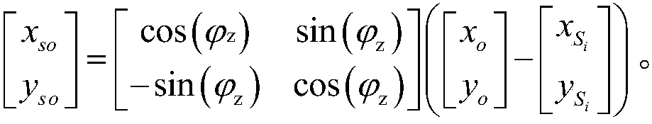
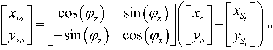
[0064] Step 3.1, first in one of the preferred particle J i There are multiple transfer points randomly distributed around the robot for simulating the position of the robot, and one of the transfer points S i Establish a random coordinate system for the origin of random coordinates, take the direction of the transfer point as the origin as the X-axis or Y-axis direction of the random coordinate system, and the coordinate positions of the grids occupied by obstacles around the random coordinate origin are in the random coordinate system Re-described in ; in specific implementation, the orientation direction of the transfer point that can also be used as the origin is the Y-axis direction of the random coordinate system, and the corresponding calculation formula can be modified adaptively, and will not be described again.


PUM


Abstract

An autonomous global relocation method for robots is provided. The method comprises steps that existing maps are rasterized; the grids with obstacles and without obstacles are assigned to different values; multiple distance data and angle data corresponding to the distance data obtained by a lidar sensor with the same position of a robot scanning external obstacles are marked on the map with the simulation robot position as the origin in the form of laser point location; and the assignment of the grid of the laser point location corresponding to each simulation robot position is integrated, robot positions are screened out, and the correct position of the robot is calculated from the initially selected simulation robot positions by a particle filtering algorithm. Through the differential assignment of grids with obstacles and without obstacles, the position of the laser point location in the map is described, and the matching degree between the lidar sensor information and the electronic map is quickly calculated, the most divergent transfer point is found as the transfer target point, and the self position can be rapidly and accurately found in a known map.

Description

technical field [0001] The invention relates to the technical field of artificial intelligence navigation, in particular to a robot autonomous global repositioning method and a robot. Background technique [0002] Mobile robot positioning is an important research direction of robotics, and it is also the key to autonomous navigation of robots, which is of great significance for improving the automation level of robots. Definition methods generally fall into two categories: absolute positioning and relative positioning. Absolute positioning requires the robot to determine its own position without specifying an initial position. Relative positioning means that the robot determines its own position under the condition of the initial position, which is the main research direction in the robot positioning process. The commonly used global relocation technology is mostly vision-based relocation technology. This technology has high calculation accuracy, but it is restricted by ha...

Claims


Application Information

Patent Timeline
Patent Type & Authority Applications(China)
IPC IPC(8): G05D1/02B25J9/16
CPCB25J9/1656B25J9/1664G05D1/0257
Inventor 刘文治谭文铨郑凯疏达李远
Owner BENEWAKE BEIJING TECH CO LTD
Why Eureka
Try Eureka