Fins for serial fin type heat exchanger

A heat exchanger, serial fin technology, applied in the fin field of serial fin heat exchanger, can solve the problems of inability to form heat transfer effect turbulent layer, poor heat exchange effect, low heat transfer coefficient of fins, etc.

Inactive Publication Date: 2009-09-23
山东光大机械制造有限公司
View PDF0 Cites 8 Cited by
  • Summary
  • Abstract
  • Description
  • Claims
  • Application Information

AI Technical Summary

Problems solved by technology

At present, the commonly used fins have a flat shape. When the medium flows through, a laminar flow layer is formed along the surface of the fin, and a turbulent flow layer with better heat transfer effect cannot be formed. The surface heat transfer coefficient of the fin is relatively low, and the heat exchange effect poor

Method used


Image

  • Fins for serial fin type heat exchanger
  • Fins for serial fin type heat exchanger
  • Fins for serial fin type heat exchanger

Examples


Embodiment 1

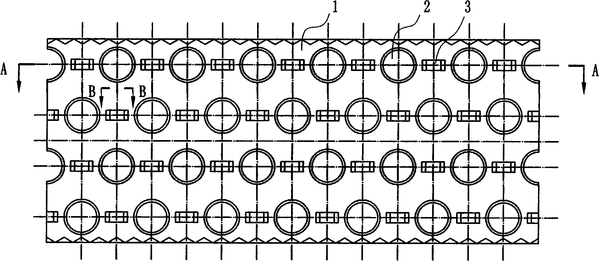
[0021] Such as figure 1 As shown, the fins of the serial-fin heat exchanger include a fin body 1, and the fin body is provided with tube holes 2 flanging to one side of the fin body 1, and the tube holes 2 between the tube holes The fin body 1 is provided with a first disturbance protrusion 3, and the side of the first disturbance protrusion 3 is provided with a cutout 31 communicating with both sides of the fin body 1. In this embodiment, each The first disturbance protrusion 3 has two cutouts 31, and the cutouts 31 are respectively arranged in the flow direction of the medium, which reduces the generation of vortex turbulence clusters.

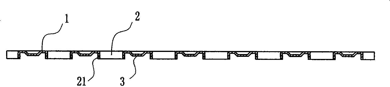
[0022] Such as image 3 As shown, the first disturbance protrusion 3 faces the direction of the flanging of the tube hole 2, and the height of the first disturbance protrusion 3 is smaller than the height of the tube hole flanging 21, which further reduces the resistance of the medium to pass through, thereby improving the fin heat transf...

Embodiment 2

[0025] This embodiment is basically the same as Embodiment 1, except that a second disturbance protrusion 5 is provided on the periphery of the tube hole 2, and the side surface of the second disturbance protrusion 5 is provided with a 1 cutouts 51 on both sides.

[0026] The second disturbing protrusion 5 faces the direction of the flange of the tube hole 2 , and the height of the second disturbing protrusion 5 is smaller than the height of the flange 21 of the tube hole.

[0027] In this embodiment, the second disturbance protrusions 5 are arc-shaped, and are evenly distributed around the tube hole 2 .

[0028] On the one hand, this embodiment enhances the strength of the tube holes, prevents the fins from being damaged during the process of connecting the fins in series, and at the same time further enhances the generation of medium turbulent flow, so that the heat exchange efficiency of the fins is greatly improved.


PUM


Abstract

The invention discloses fins for a serial fin type heat exchanger. A fin body between pipe holes is provided with a first disturbance protrusion, thereby improving the rigidity of the fin body and playing a disturbance role in media which flow through the surface of the fin body, and turbulent heat transfer is arisen so as to ensure that the surface heat transfer coefficient of the fins is greatly improved. But at the same time, large numbers of medium vortex turbulent flow clusters are formed so as to increase the pressure loss when the media pass through a core body. The side face of the first disturbance protrusion is provided with a notch which is communicated with both sides of the fin body so as to ensure that partial media enter the other side of the fin body through the notch, thereby solving the technical problem of the vortex turbulent flow clusters and further improving the heat exchange efficiency of the fins.

Description

technical field [0001] The invention relates to the technical field of heat exchangers, in particular to fins of a series fin heat exchanger. Background technique [0002] Such as Figure 7 and Figure 8 As shown, the fins of the existing serial fin heat exchanger are provided with a plurality of tube holes on each fin, and a tube hole flange is provided on one side of the tube holes. Among them, the shape of the fins has a great influence on the heat exchange performance of the heat exchanger. At present, the commonly used fins have a flat shape. When the medium flows through, a laminar flow layer is formed along the surface of the fin, and a turbulent flow layer with better heat transfer effect cannot be formed. The surface heat transfer coefficient of the fin is relatively low, and the heat exchange effect poor. Contents of the invention [0003] The technical problem to be solved by the present invention is to provide a fin of a serial fin heat exchanger with simple...

Claims


Application Information

Patent Timeline
Patent Type & Authority Applications(China)
IPC IPC(8): F28F3/00F28F13/12
Inventor 蒋积良宋晓兵张永健
Owner 山东光大机械制造有限公司
Why Eureka
Try Eureka