Ground electrode circuit protective system and device of high-voltage DC transmission system

A high-voltage direct current transmission and line protection technology, applied in emergency protection circuit devices, electrical components, electrical program control and other directions, can solve problems such as accelerated corrosion of the tower grounding grid, human and animal damage to the grounding pole and tower step voltage, and disconnection of the grounding pole line.

Active Publication Date: 2009-09-23
CSG EHV POWER TRANSMISSION
View PDF0 Cites 46 Cited by
  • Summary
  • Abstract
  • Description
  • Claims
  • Application Information

AI Technical Summary

Benefits of technology

This patented technology uses an improved protective system that can accurately detect any potential problems or failures on both sides of power transmission systems without interrupting their operation altogether. It does this by measuring changes caused by differences between voltage levels at different points along each side's wires. By comparing these measurements against predetermined limits, it determines if there are any issues affecting the safety of the affected equipment.

Problems solved by technology

This patented describes a method used during maintenance operations on electricity transmitting systems called Ground Electrodes' Neutralization Batteries (GEMs). These grids have multiple polygonal connections made up by connecting conductive rods together. By controlling these connections, they act like capacitors but without being affected by any external factors like weather conditions. They also prevent excessive voltages caused by electrical surges. Additionally, this design helps protect against accidentally closing downstream circuits while still allowing proper operation under all possible circumstances. Overall, these technical features improve the performance and security of the Grounding Layer Protect System (GSPS) in electronic equipment utilized within industrial applications including power generation systems.

Method used


Image

  • Ground electrode circuit protective system and device of high-voltage DC transmission system
  • Ground electrode circuit protective system and device of high-voltage DC transmission system
  • Ground electrode circuit protective system and device of high-voltage DC transmission system

Examples


Embodiment Construction

[0025] The specific implementation mode is a specific embodiment for implementing the present invention, and the present invention is not limited by the circuit of the specific embodiment.

[0026] see Figure 2-5 , a specific embodiment of the ground electrode line protection circuit of the present invention is as follows:

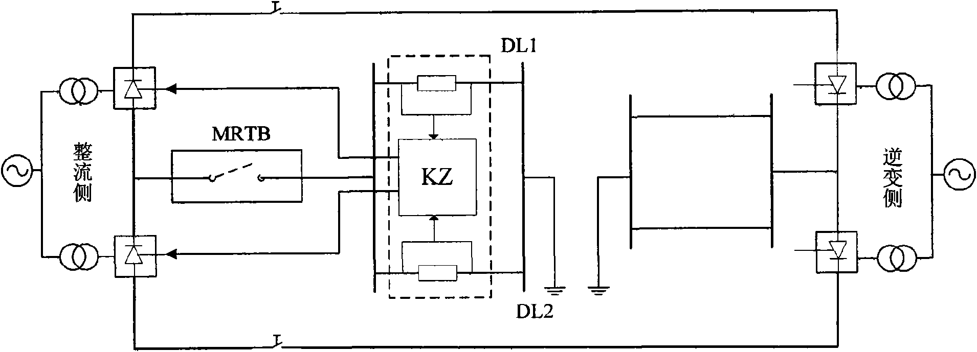
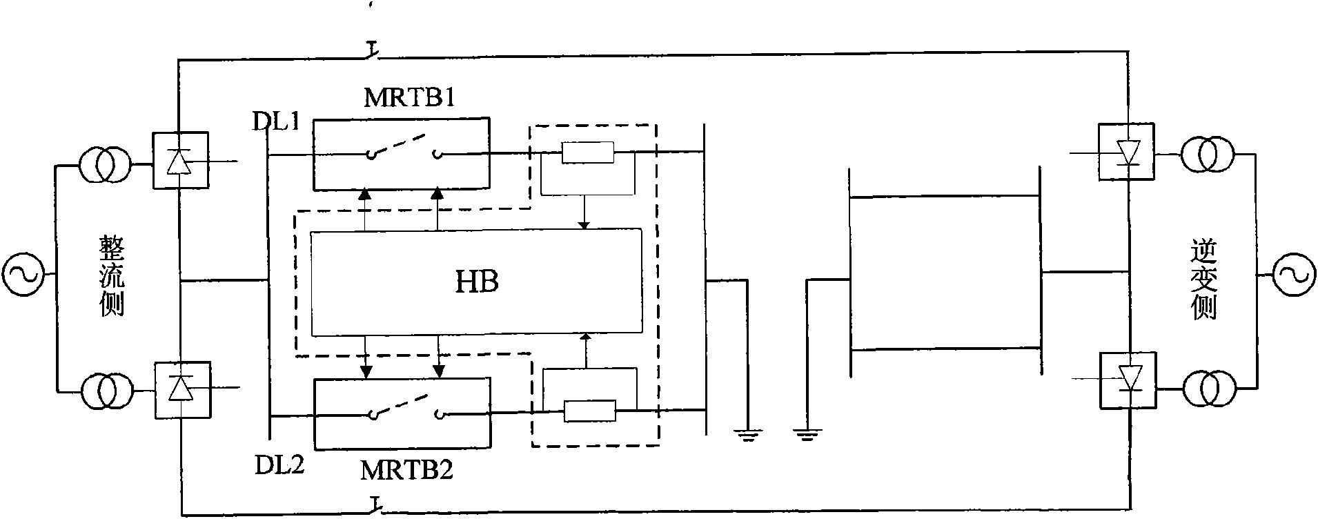
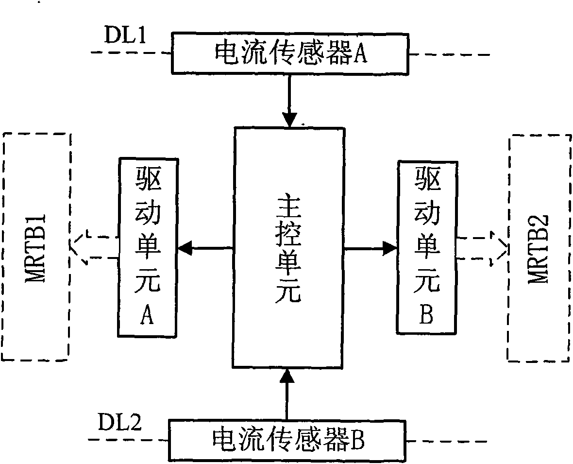
[0027] see figure 2 , one end of two high-voltage DC circuit breakers MRTB1 and MRTB2 is connected in parallel to the neutral point of the DC side of the bipolar converter valve of the rectification side converter station, and the other end is connected in series with a grounding electrode line DL1 and DL2 respectively, and then connected to the grounding electrode connection; the two current sensing terminals in the unbalanced current protection device HB are respectively connected to the two grounding electrode lines DL1 and DL2, and the unbalanced current protection device HB ( figure 2 The two output terminals of the protection control signal show...


PUM


Abstract

The invention relates to a ground electrode circuit grounding protective system of a high-voltage DC transmission system. The system is provided with two parallel ground electrode circuits respectively connected in series with a high-voltage DC breaker, sets an allowable range of current differences of two ground wires and an allowable range of the subtraction of the line current sum of the two ground wires from the line current difference of the two ground wires and then sequentially executes the following control program: (1), reading currents of the two ground wires; (2), judging and comparing whether an absolute value of the current difference of two ground wires is larger than the allowable range thereof, if the absolute value is not larger than the allowable range, returning to the step (1); if the absolute value is larger than the allowable range, (3) then, judging whether the subtraction of the line current sum of the two ground wires from the line current difference of the two ground wires is smaller than or equal to the allowable range; if the subtraction is smaller than or equal to the allowable range, returning to the step (1); and if the subtraction is not smaller than or equal to the allowable range, enabling the high-voltage DC breaker which is connected in series with the ground wire with larger line current to trip and terminate the program. The system can avoid the imbalance of the ground electrode circuits due to the failures of the ground electrode circuits and protects the caused DC transmission system to be closed down.

Description


Claims


Application Information

Patent Timeline
Owner CSG EHV POWER TRANSMISSION
Why Eureka
Try Eureka