Automatical fishing bracket

An automatic and stand-seat technology, applied in the field of fishing utensils, can solve the problems of increasing spring strength, unadjustable elastic force, short service life, etc., and achieve the effect of prolonging service life, strong spring elasticity and long service life

Inactive Publication Date: 2009-09-30
庄瑞明
View PDF0 Cites 4 Cited by
  • Summary
  • Abstract
  • Description
  • Claims
  • Application Information

AI Technical Summary

Problems solved by technology

[0002] Most of the automatic fishing devices currently in use have the following problems: 1. Insensitive, can not be thrown far, only short fishing rods can be used, automatic fishing rods, automatic fishing brackets, automatic fishing devices, etc. have no mechanical and labor-saving design, and the fishing rods cannot be lifted If the line cannot be pulled, increase the force of the spring to make the trigger bear a lot of pressure. Only big fish or fish news can pull the trigger. If the fish can pull the insensitive trigger, it means that the bait is deep. Can be caught without automatic fishing, the function of automatic fishing is greatly reduced
2. The length of the fishing rod is limited, and there is no mechanical and labor-saving design for automatic fishing, which makes it difficult to lift a fishing rod longer than 2 meters, and the line cannot be pulled
3. The original fishing rod cannot be used
4. The sensitivity cannot be adjusted, and the sensitivity is the same for big and small fish, resulting in the situation of over and under
5. The elastic force cannot be adjusted. Both big and small fish have the same elastic force, resulting in over and under
6. Labor-intensive, without mechanical and labor-saving design, if the fishing rod cannot be lifted or the line cannot be pulled, the strength of the spring will be increased, resulting in laborious use
7. It is not safe, the spring is too strong and you will be injured if you accidentally hit it
8. The service life is short, the spring is too strong, the whole machine is overloaded, and it is easy to break down

Method used


Image

  • Automatical fishing bracket
  • Automatical fishing bracket

Examples


Embodiment Construction

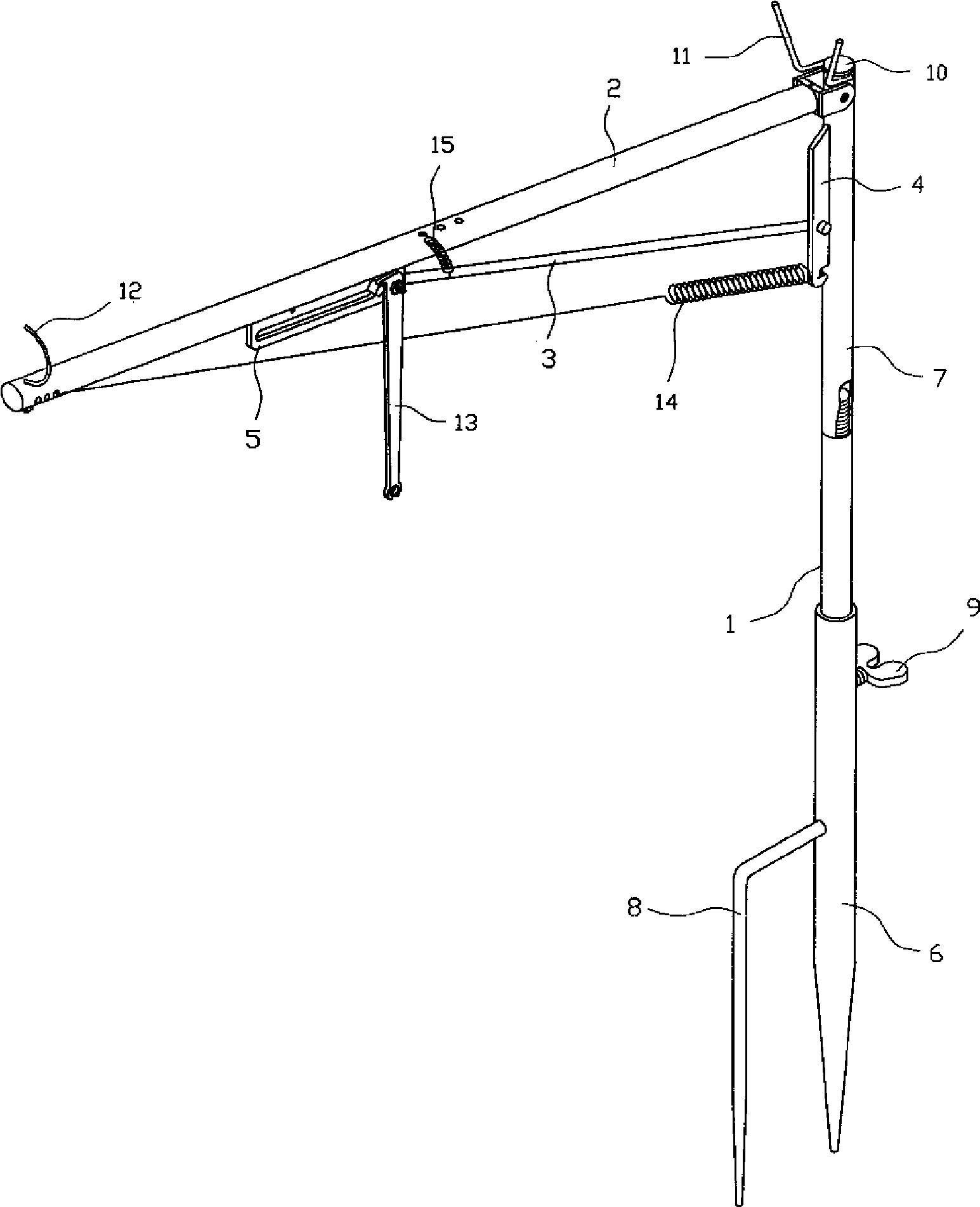
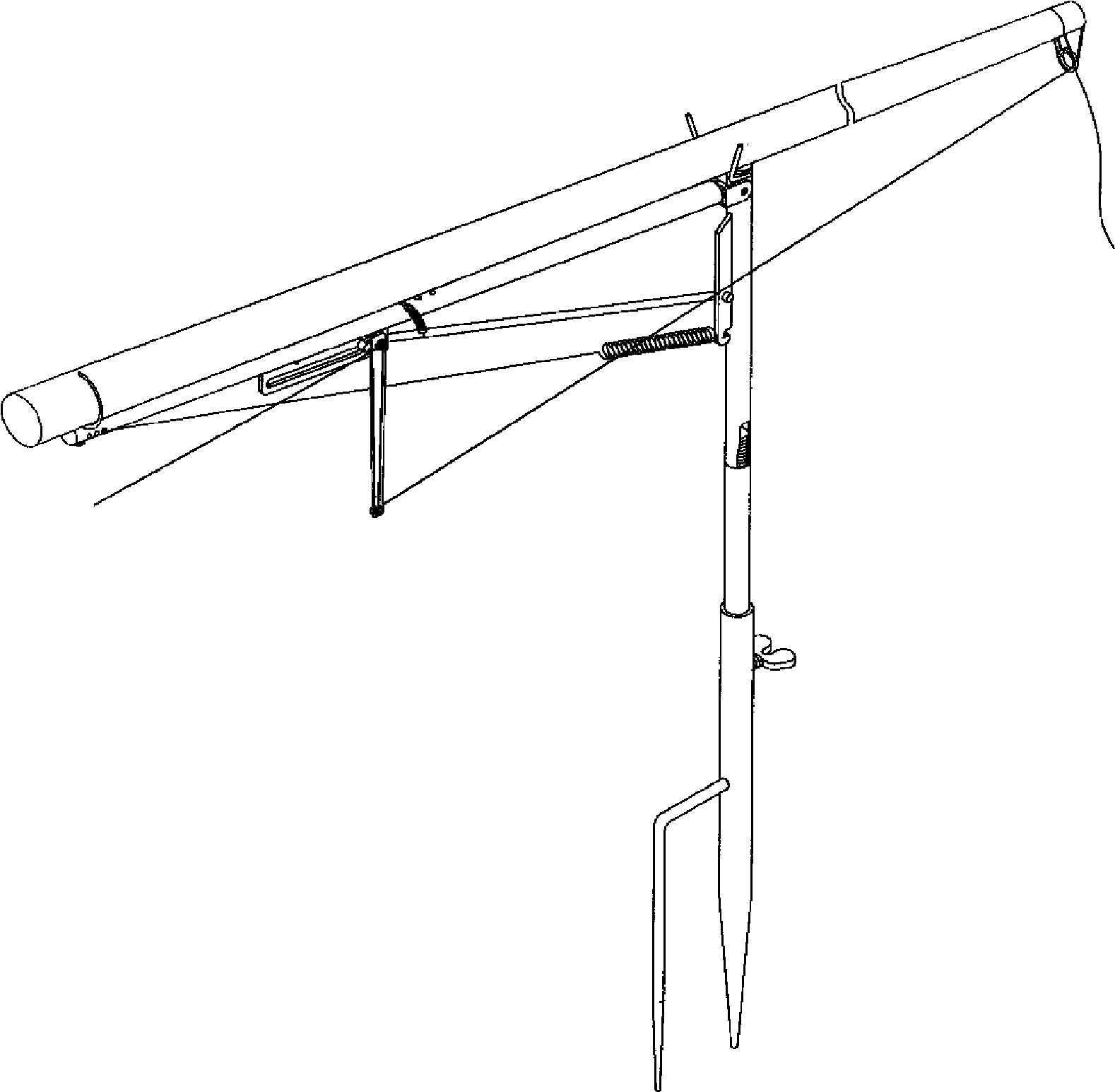
[0025] Depend on figure 1 , 2 It can be seen that the present invention includes:

[0026] A support 1 inserted into the ground and fixed, a force arm 2 supporting the fishing rod, a pull rod 3 connecting the support 1 and the force arm 2, and a spring that pulls the force arm 2 to make the fishing rod spring up quickly 14, of which:

[0027] The force applying arm 2 is arranged on the top of the support 1 , and the force applying arm 2 is movably connected with the support 1 .

[0028] One end of the pull rod 3 is connected to the baffle plate 4 provided on one side of the pole 1, and the other end is connected to the slide plate 5 provided on the arm 2, and the pull rod 3 can slide back and forth in the slide rail groove of the slide plate 5.

[0029] The slide plate 5 is welded on the force arm 2, and the middle part of the slide plate 5 has a strip-shaped slide rail groove, and the upper part of the slide rail groove has a hole for piercing a fishing line. Trigger 13 f...


PUM


Abstract

The invention relates to an automatical fishing bracket comprising a bracket which is inserted into the ground for fixing, a force applying arm for supporting the fishing pole, a pull rod connecting the bracket and the force applying arm and a spring to pull the force applying arm to quickly bounce the fishing pole, wherein the force applying arm is arranged on the top of the bracket and is moveable connected with the bracket. One end of the pull rod is connected with a baffle plate arranged at one side of the strut and the other end is connected with a slideing board arranged on the force applying arm. The pull rod can slide front and back in a slider groove of the sliding board. The sliding board is welded on the force applying arm. An elongated slider groove is arranged in the middle of the slide board. A pore from which the fishing thread is penetrated is arranged at the upper portion of the slider groove. A trigger for towing the fishing thread is movably connected at one side of the back of the sliding board. One end of the spring is hooked on the baffle plate and the other end is hooked in an adjusting pore on the force applying arm. The spring is detachably arranged between the bracket and the force applying arm. The invention is sensitive, safe, labor saving, beautiful and portable and has the simple structure and long service life.

Description

technical field [0001] The invention relates to a fishing appliance, in particular to an automatic fishing support which can control a fishing rod to automatically pull up a fishing line after a fish bites a hook under unmanned control. Background technique [0002] Most of the automatic fishing devices currently in use have the following problems: 1. Insensitive, can not be thrown far, only short fishing rods can be used, automatic fishing rods, automatic fishing brackets, automatic fishing devices, etc. have no mechanical and labor-saving design, and the fishing rods cannot be lifted If the line cannot be pulled, increase the force of the spring to make the trigger bear a lot of pressure. Only big fish or fish news can pull the trigger. If the fish can pull the insensitive trigger, it means that the bait is deep. It can be caught without automatic fishing, and the function of automatic fishing is greatly reduced. 2. The length of the fishing rod is limited, and there is n...

Claims


Application Information

Patent Timeline
Patent Type & Authority Applications(China)
IPC IPC(8): A01K97/11
Inventor 庄瑞明
Owner 庄瑞明
Why Eureka
Try Eureka