Thermal management system for embedded environment and method for making same

A technology of environment and cooling system, applied in the field of thermal management system of embedded environment

Inactive Publication Date: 2009-09-30
GENERAL ELECTRIC CO
View PDF3 Cites 1 Cited by
  • Summary
  • Abstract
  • Description
  • Claims
  • Application Information

AI Technical Summary

Problems solved by technology

Designing a thermal management system to cool embedded electronics is a serious challenge given space constraints

Method used


Image

  • Thermal management system for embedded environment and method for making same
  • Thermal management system for embedded environment and method for making same
  • Thermal management system for embedded environment and method for making same

Examples


Embodiment Construction

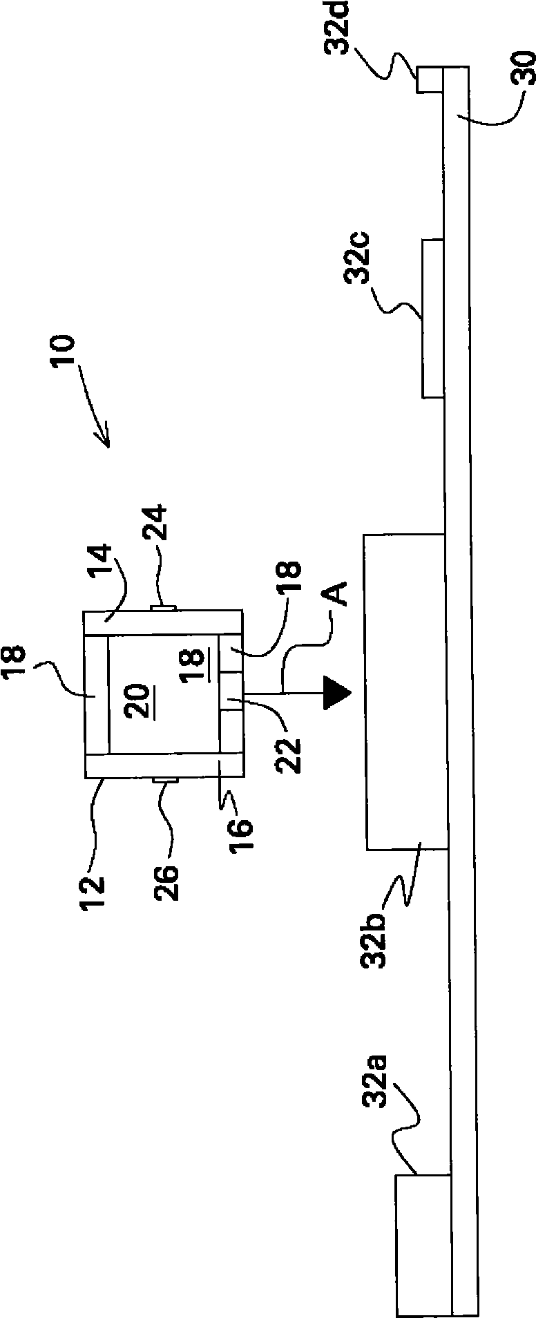
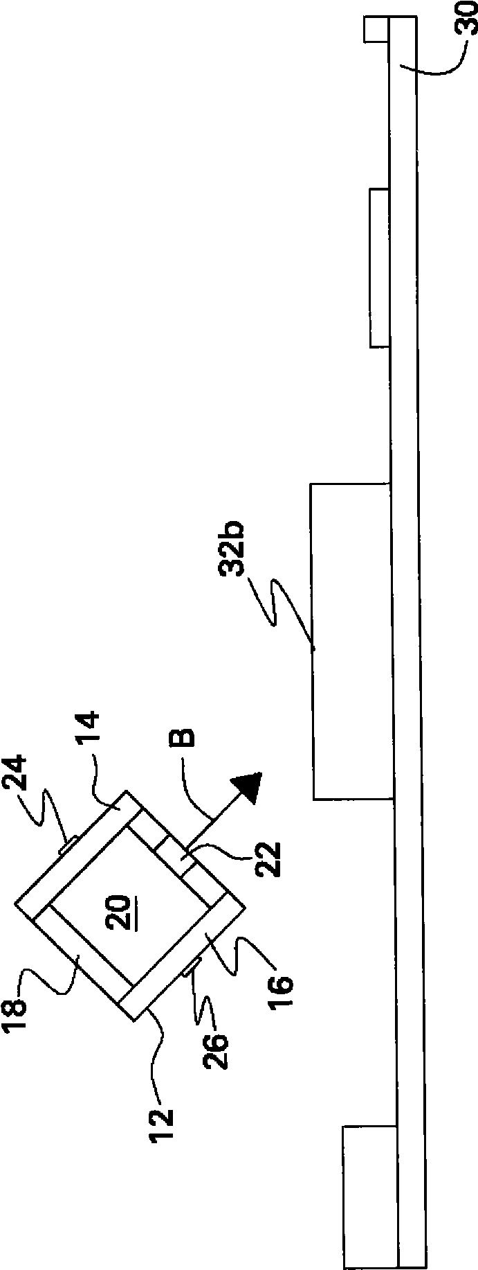
[0018] refer to figure 1 and 2 , the thermal management system 10 shown includes a pleumo-jet 12 shown in cross-section and positioned adjacent a printed circuit board assembly (PCA) 30 having a plurality of electronic components 32a requiring cooling -d. While PCA 30 has been described with reference to embodiments of the present invention, it should be understood that thermal management system 10 may be used in any suitable embedded environment and that reference to PCA 30 is described for ease of illustration only. The PCA 30 may be used in a heated environment in any number of small electronic devices, such as, for example, microcontrollers, programmable logic controllers (PLCs), portable computers, mobile phones, personal digital assistants (PDAs), personal pocket computers, and the like. Primo injector 12 is sized for its purpose and is generally meso-scale or micro-scale.

[0019] Primo injectors 12 are positioned such that a pulsed fluid flow of ambient air is gener...


PUM


Abstract

A thermal management system for an embedded environment is described. The thermal management system includes a pleumo-jet that has at least one wall defining a chamber, at least one piezoelectric device on the at least one wall, and a compliant material within the at least one wall and encompassing the chamber. The compliant material has at least one opening providing fluid communication between said chamber and the embedded environment. A cooling system is also described. A method for making a pleumo-jet is also described.

Description

technical field [0001] The present invention relates generally to thermal management systems, and more particularly to thermal management systems for embedded environments. Background technique [0002] Environments with embedded electronic systems, hereinafter referred to as embedded environments or heated environments, present challenges for thermal management. Such systems generate waste heat as part of their normal operation, which must be removed for the embedded electronics to function properly and remain reliable. Designing a thermal management system to cool embedded electronics is a serious challenge given the limited space. Examples of embedded electronic systems include microcontrollers, programmable logic controllers (PLCs), operator interface computers, portable computers, mobile phones, personal digital assistants (PDAs), personal pocket computers, and other electronic devices. For thermal management systems , only limited space is available. It is known to ...

Claims


Application Information

Patent Timeline
Patent Type & Authority Applications(China)
IPC IPC(8): G06F1/20
CPCG06F1/20Y10S165/908Y10T29/4935Y10T29/49826H05K7/20
Inventor 梅麦特·阿里克查尔斯·F·沃尔夫约根·V·厄特卡查尔斯·E·西利戴维·S·斯莱顿威廉·H·利肯巴克
Owner GENERAL ELECTRIC CO
Why Eureka
Try Eureka