Battery pack enclosure with controlled thermal runaway release system

a technology of battery pack and release system, which is applied in the direction of battery/cell propulsion, cell components, batteries, etc., can solve the problems of specialized handling and operating requirements, further increase in reaction rate and heat generation, and the switch in drive train technology is not without technological hurdles, etc., to achieve the effect of lowering the melting poin

Active Publication Date: 2010-10-28
TESLA INC
View PDF17 Cites 81 Cited by
  • Summary
  • Abstract
  • Description
  • Claims
  • Application Information

AI Technical Summary

Problems solved by technology

This switch in drive train technology is not, however, without its technological hurdles as the use of an electric motor translates to the need for inexpensive batteries with high energy densities, long operating lifetimes, and operable in a wide range of conditions.
While current rechargeable battery technology is able to meet the demands of the automotive industry, the relatively unstable nature of the chemistries used in such batteries often leads to specialized handling and operating requirements.
For example, rechargeable batteries such as lithium-ion cells tend to be more prone to thermal runaway than primary cells, thermal runaway occurring when the internal reaction rate increases to the point that more heat is being generated than can be withdrawn, leading to a further increase in both reaction rate and heat generation.
Thermal runaway may be initiated by a short circuit within the cell, improper cell use, physical abuse, manufacturing defects, or exposure of the cell to extreme external temperatures.
In the case of a battery pack used in an electric vehicle, a severe car crash may simultaneously send multiple cells within the battery pack into thermal runaway.
As a result, power from the battery pack is interrupted and the system employing the battery pack is more likely to incur extensive collateral damage due to the scale of thermal runaway and the associated release of thermal energy.

Method used


Image

  • Battery pack enclosure with controlled thermal runaway release system
  • Battery pack enclosure with controlled thermal runaway release system
  • Battery pack enclosure with controlled thermal runaway release system

Examples


Embodiment Construction

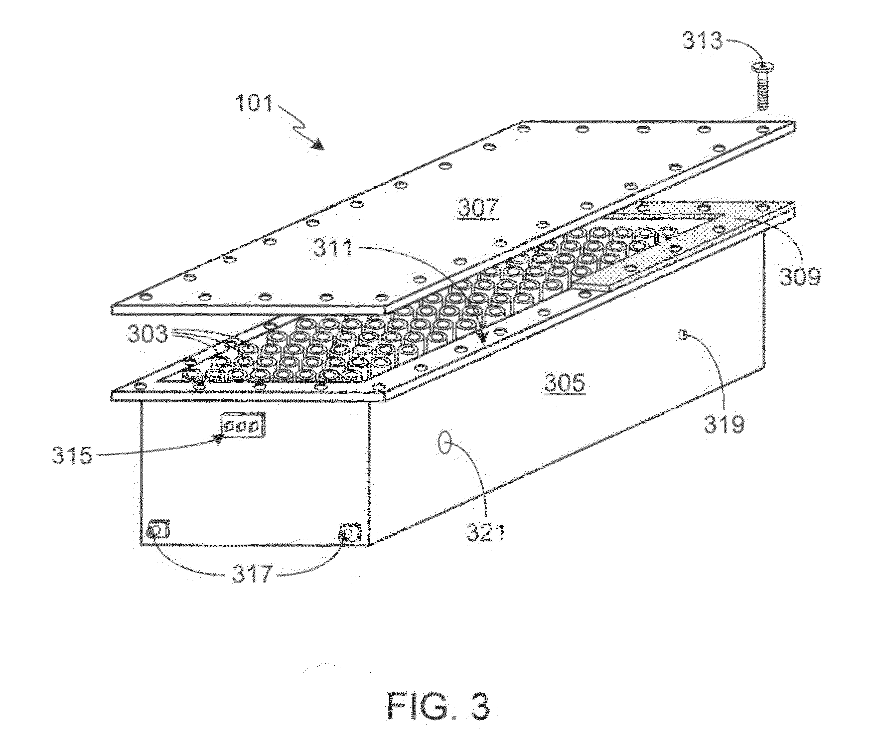
[0031]In the following text, the terms “battery”, “cell”, and “battery cell” may be used interchangeably and may refer to any of a variety of different rechargeable cell chemistries and configurations including, but not limited to, lithium-ion (e.g., lithium iron phosphate, lithium cobalt oxide, other lithium metal oxides, etc.), lithium-ion polymer, nickel metal hydride, nickel cadmium, nickel hydrogen, nickel zinc, silver zinc, or other battery type / configuration. The term “battery pack” as used herein refers to multiple individual batteries contained within a single piece or multi-piece housing, the individual batteries electrically interconnected to achieve the desired voltage and capacity for a particular application. The term “electric vehicle” as used herein refers to either an all electric vehicle, also referred to as an EV, plug-in hybrid vehicles, also referred to as a PHEV, or a hybrid vehicle (HEV), a hybrid vehicle utilizing multiple propulsion sources one of which is a...


PUM

PropertyMeasurementUnit
melting temperatureaaaaaaaaaa
temperatureaaaaaaaaaa

Abstract

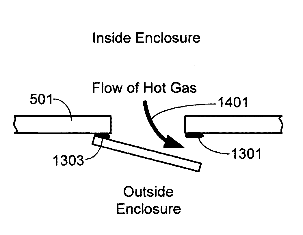
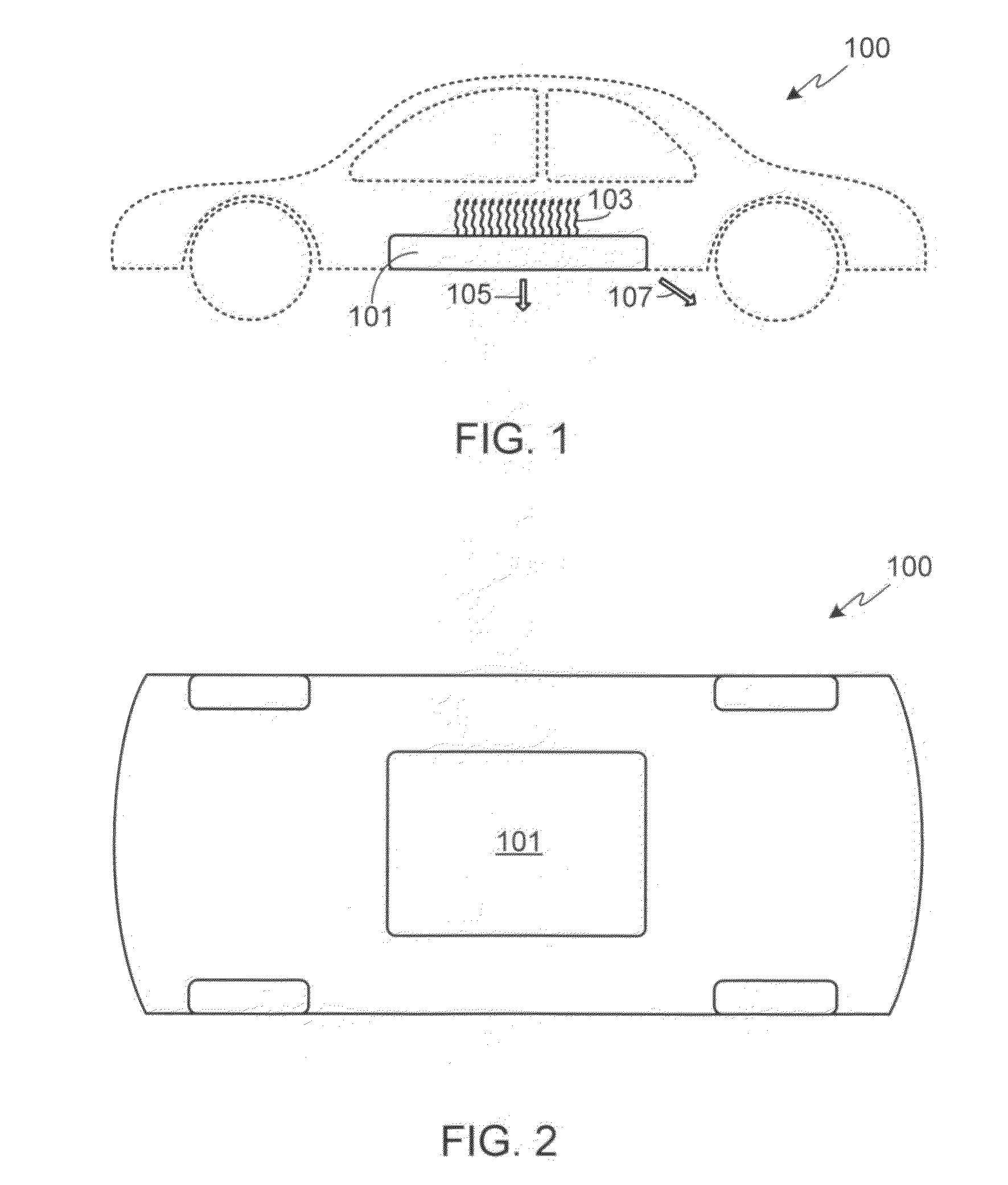
A battery pack thermal management system is provided that is comprised of at least one enclosure failure port integrated into at least one wall of a battery pack enclosure, where the enclosure failure port(s) remains closed during normal operation of the battery pack, and opens during a battery pack thermal runaway event, thereby providing a flow path for hot gas generated during the thermal runaway event to be exhausted out of the battery pack enclosure in a controlled fashion.

Description

CROSS-REFERENCES TO RELATED APPLICATIONS[0001]This application is a continuation-in-part of U.S. patent application Ser. No. 12 / 386,684, filed Apr. 22, 2009, the disclosure of which is incorporated herein by reference for any and all purposes.FIELD OF THE INVENTION[0002]The present invention relates generally to battery packs and, more particularly, to a system for controlling the release of thermal energy and hot gas from a battery pack undergoing thermal runaway.BACKGROUND OF THE INVENTION[0003]There is currently a trend in the automotive industry to replace combustion engines with electric motors or a combination of an electric motor and a combustion engine, thereby substantially reducing the environmental impact of automobiles by reducing (i.e., hybrids) or completely eliminating (i.e., electric vehicles) car emissions. This switch in drive train technology is not, however, without its technological hurdles as the use of an electric motor translates to the need for inexpensive b...

Claims


Application Information

Patent Timeline
Patent Type & Authority Applications(United States)
IPC IPC(8): H01M10/50B60L50/64
CPCH01M2/08H01M2/1077H01M2/1094H01M2/1235H01M2200/10H01M2/1252H01M10/5016H01M10/504H01M10/5087H01M2/1241H01M10/625H01M10/653H01M10/658B60K1/04B60K2001/0438Y02E60/10H01M50/24H01M50/342H01M50/3425H01M50/249B60L50/64H01M50/367H01M50/186H01M50/224H01M50/276H01M50/213Y02T10/70
Inventor HERMANN, WESTON ARTHURPRILUTSKY, ALEXMEHTA, VINEET HARESH
Owner TESLA INC
Why Eureka
Try Eureka