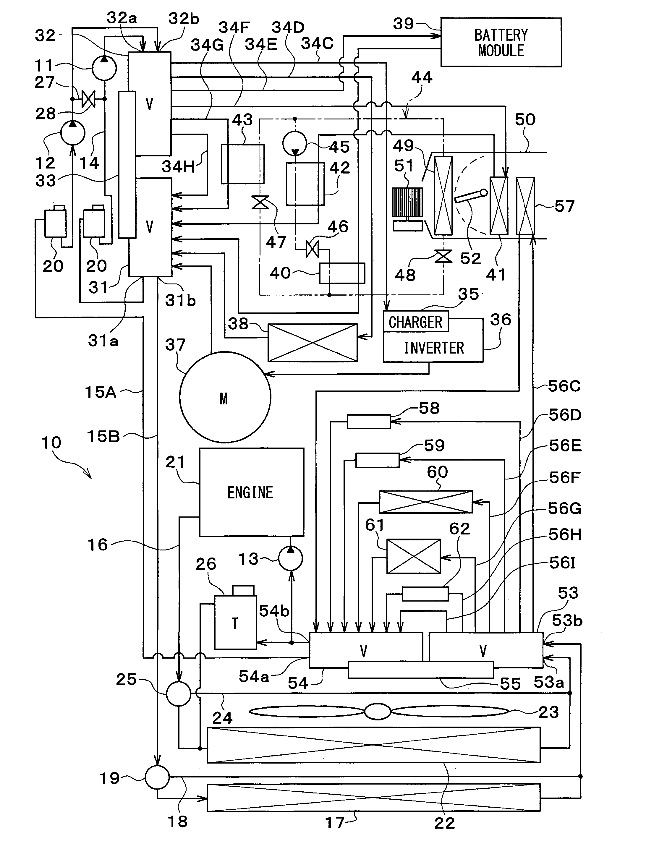
Vehicle heat management system
a technology for heat management systems and vehicles, applied in the direction of machines/engines, electric devices, battery/fuel cell control arrangements, etc., can solve the problems of complicated configuration of the entire system, and achieve the effect of simplifying the configuration of the vehicle heat management system
- Summary
- Abstract
- Description
- Claims
- Application Information
AI Technical Summary
Benefits of technology
Problems solved by technology
Method used
Image
Examples
fourth embodiment
[0171]An operation mode, which warms up oil by the heat stored in the first heat storage device, will be described in a fourth embodiment.
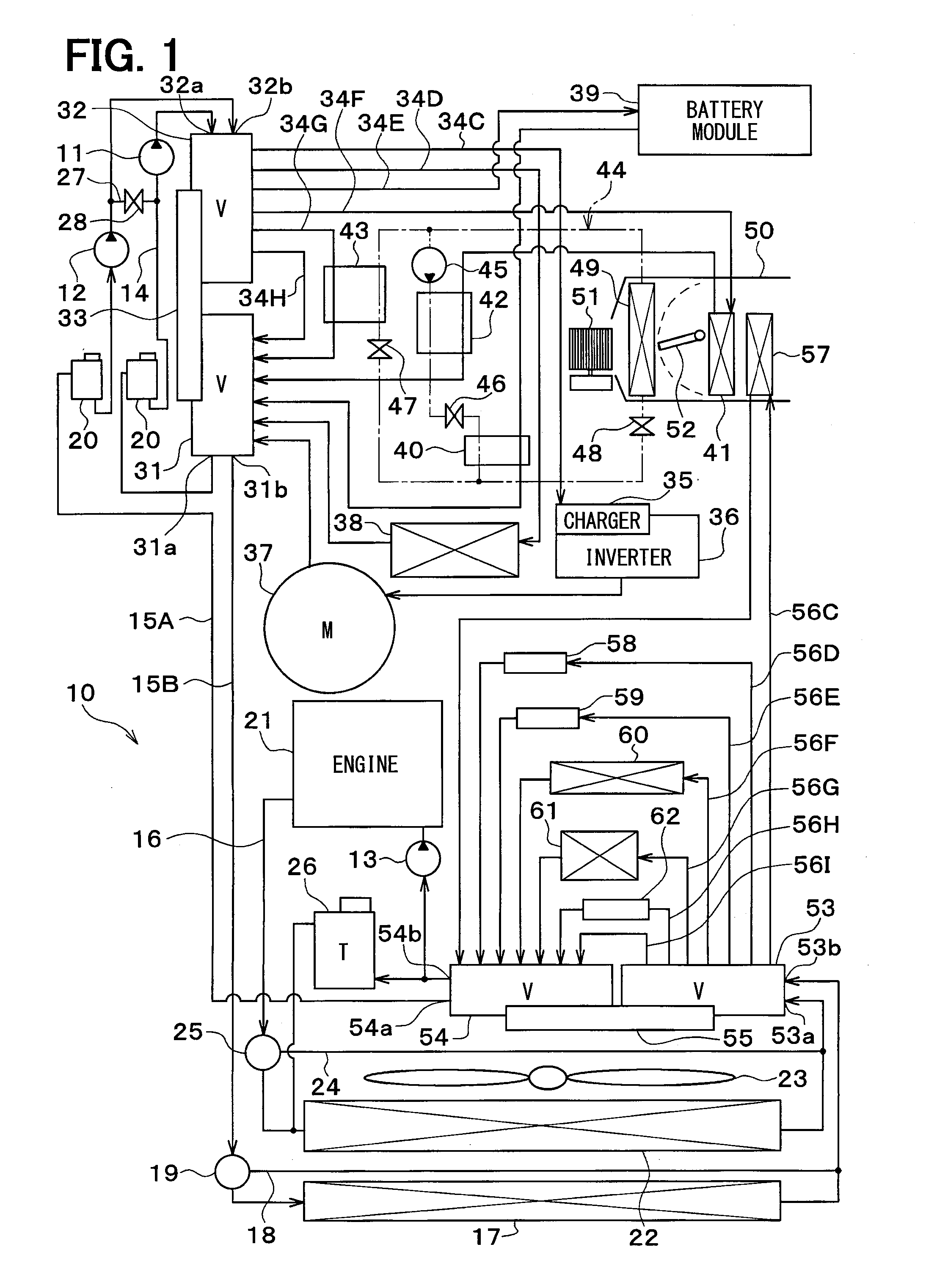
[0172]When the temperature of a coolant flowing in the first heat storage device (the battery module 39 in the example of FIG. 13) is equal to or higher than the temperature of oil flowing in the coolant-oil heat exchanger 61 and is equal to or higher than a predetermined temperature, a first cooling circuit (left broken line), a second cooling circuit (thick solid line), and a third cooling circuit (right broken line) are formed as shown in FIG. 13 and the three-way valve 19 is controlled so that a coolant flows into the bypass flow passage 18 in the second cooling circuit. To facilitate understanding, the simplified configuration of the vehicle heat management system 10 is shown in FIG. 13.
[0173]The first heat storage device (the battery module 39 in the example of FIG. 13) of the first heat exchange target device group 81 is connected to the se...
fifth embodiment
[0181]An operation mode, which warms up the engine by the heat stored in the first heat storage device, will be described in a fifth embodiment.
[0182]In this operation mode, a first cooling circuit (thick solid line) and a second-third connected cooling circuit (thick one-dot chain line) are formed as shown in FIG. 14 and the three-way valves 19 and 25 are controlled so that a coolant flows into the bypass flow passages 18 and 24 in the second-third connected cooling circuit. To facilitate understanding, the simplified configuration of the vehicle heat management system 10 is shown in FIG. 14.
[0183]The first heat storage device (the battery module 39 in the example of FIG. 14) of the first heat exchange target device group 81 is connected to the second-third connected cooling circuit, and the coolant-oil heat exchanger 61 of the second heat exchange target device group 82 is connected to the second-third connected cooling circuit.
[0184]Further, when the temperature of oil is lower t...
sixth embodiment
[0189]An operation mode, which warms up oil by the operation of a heat pump absorbing heat from the first heat storage device, will be described in a sixth embodiment. This operation mode is performed under a temperature condition where oil cannot be directly warmed up by the heat stored in the first heat storage device.
[0190]Specifically, when the temperature of a coolant flowing in the first heat storage device (the battery module 39 in the example of FIG. 15) is equal to or lower than the temperature of oil flowing in the coolant-oil heat exchanger 61 and is equal to or lower than a predetermined temperature, a first cooling circuit (thick solid line) and a second cooling circuit (thick one-dot chain line) are formed as shown in FIG. 15. To facilitate understanding, the simplified configuration of the vehicle heat management system 10 is shown in FIG. 15.
[0191]When the allowable temperature of a device, which generates heat, (the inverter 36 in the example of FIG. 15) of the firs...
PUM
 Abstract
Description
Claims
Application Information
 - R&D
- Intellectual Property
- Life Sciences
- Materials
- Tech Scout
- Unparalleled Data Quality
- Higher Quality Content
- 60% Fewer Hallucinations
Browse by: Latest US Patents, China's latest patents, Technical Efficacy Thesaurus, Application Domain, Technology Topic, Popular Technical Reports.
© 2025 PatSnap. All rights reserved.Legal|Privacy policy|Modern Slavery Act Transparency Statement|Sitemap|About US| Contact US: help@patsnap.com


