Intelligent multi-loop thermal management system for an electric vehicle

Inactive Publication Date: 2018-06-28
BORDRIN MOTOR CORP
View PDF4 Cites 82 Cited by
  • Summary
  • Abstract
  • Description
  • Claims
  • Application Information

AI Technical Summary

Benefits of technology

[0030]Benefits of the present invention are: The thermal management system forms a plurality of loops capable of automatic regulation by configuring a plurality of three-way valves, straight-through valves, four-way valves, and electronic expansion valve. Loops satisfying different cooling or heating requirements may be formed by regulating the degrees of opening of the electronic expansion valve, the four-way valves, the three-way valve, and the straight-through valve. These loops may be selectively opened or closed according to characteristics and working states of the battery pack, the electric-drive module, and the passenger compartment air conditioner of the electric vehicle. In this way, heat equalization of the electric vehicle is maintained, and efficient operation of the electric vehicle is improved.
[0031]The system provides energy saving, and the loops

Problems solved by technology

However, the development of electric vehicles is presently facing some challenges.
For example, electric vehicles need a relatively long time for charging their power batteries and have limited range with a fully-charged battery in comparison with fully fueled conventional automobiles.
Many of the electric vehicles currently available in the market contain thermal management systems that are not energy efficient.
For example, an air-conditioning system, a cooling system for the battery-pack, and a cooling system for the electric-drive-module may not be sufficiently linked and operated in a synergetic manner with respect to heat or energy transfers between them.
Cooling of a battery pack usually relies excessively on air-conditioning refrigeration or alternatively via a battery radiator added in front of a condenser.
This negatively impacts the performance of air conditioning and effectiveness of heat dissipation of the electric-drive module, lower drive efficiency and drivability, increase wind resistance, an

Method used


Image

  • Intelligent multi-loop thermal management system for an electric vehicle
  • Intelligent multi-loop thermal management system for an electric vehicle
  • Intelligent multi-loop thermal management system for an electric vehicle

Examples


example 2

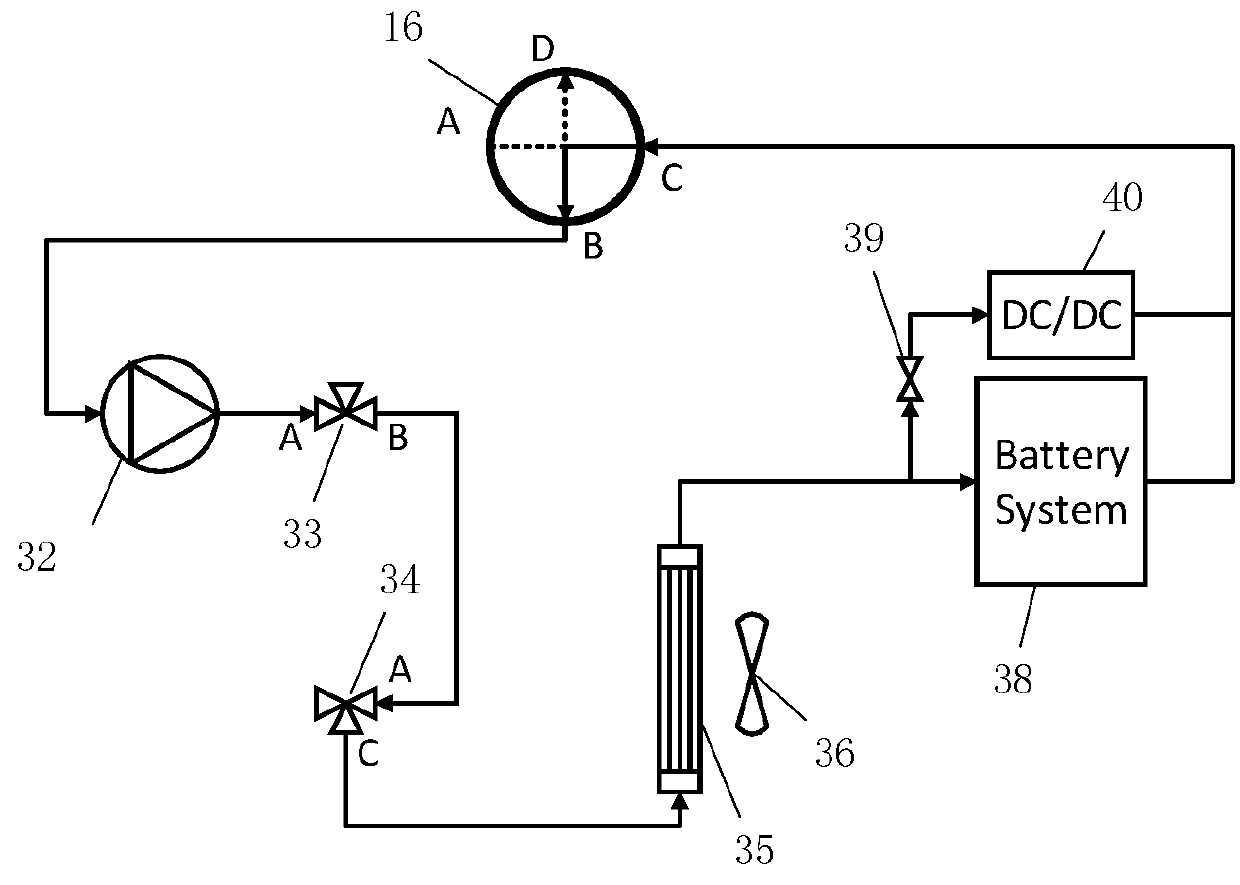
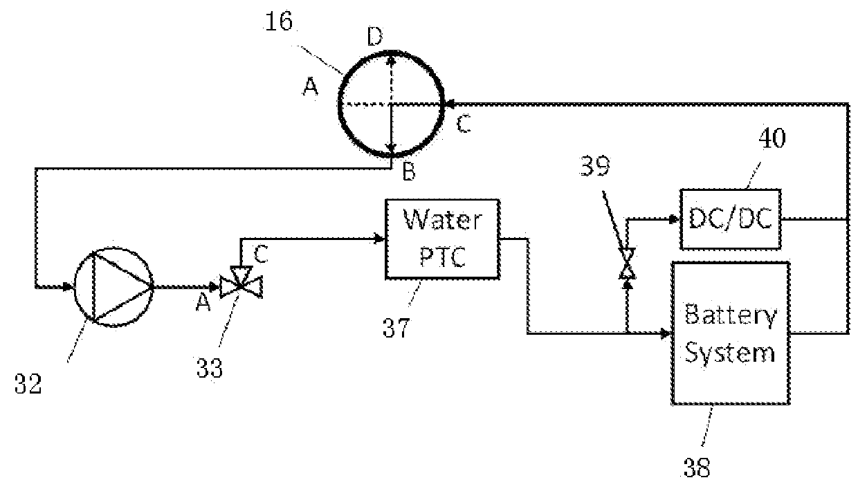
[0069]When an electric vehicle is running, the temperature of a battery pack 38 needs to be maintained within a proper temperature range. For a lithium ion battery, it is usually considered that when the temperature of the lithium ion battery is between 0° C. and 40° C., the temperature is within a reasonable range, and is neither excessively high nor excessively low. When the temperature of the battery pack 38 is within the reasonable range but a temperature difference between cells is excessively large and exceeds a reasonable temperature difference (it is usually considered that a temperature difference between cells of less than 5° C. is reasonable), temperature equalization needs to be performed on the battery pack 38.

[0070]Referring to FIG. 2, a coolant is driven by the fourth electric water pump 32, first flows to an inlet A of the third three-way valve 33 and then flows out from an outlet C, then flows through the second PTC heater 37 (in this case, the second PTC heater 37 ...

example 3

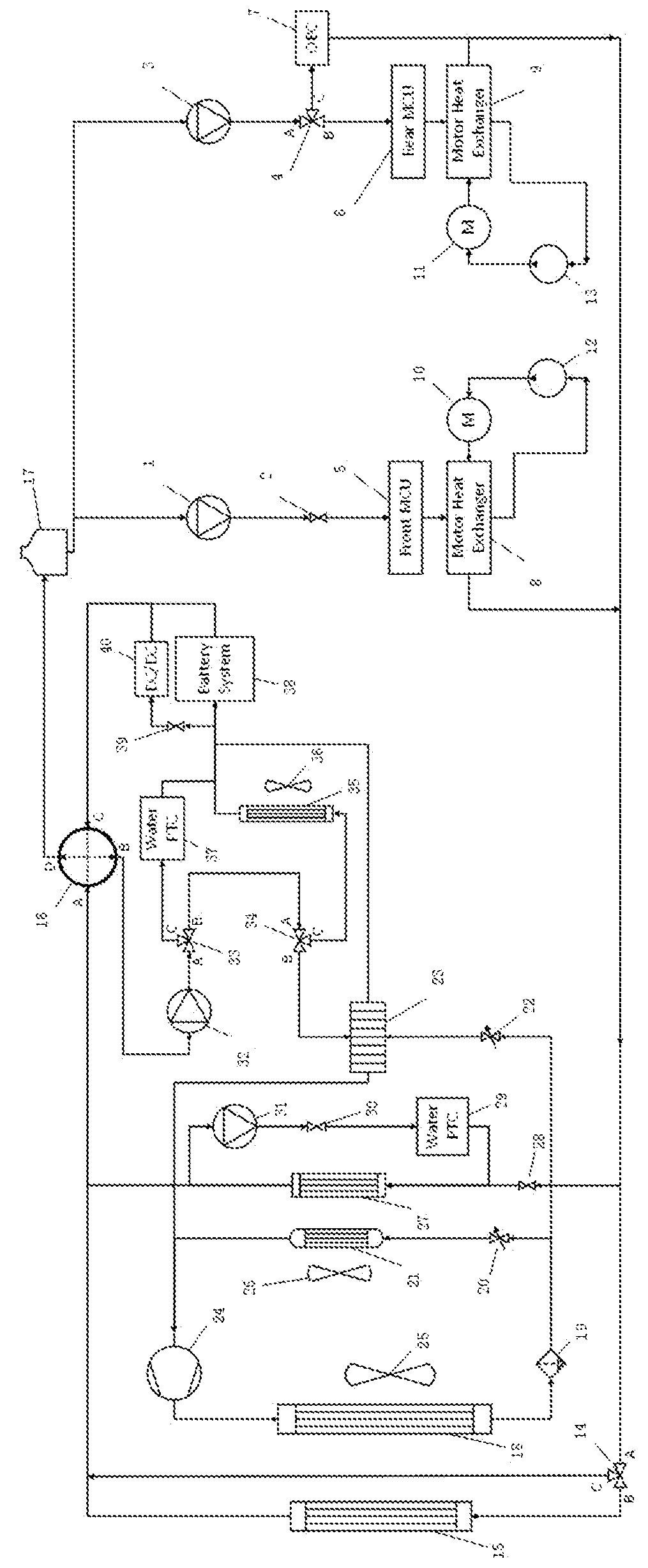
[0074]Referring to FIG. 6 and FIG. 7, the first electric oil pump 12, the first drive motor 10, and the first heat exchanger 8 are connected in series to form a first drive-motor oil-cooling loop. The second electric oil pump 13, the second drive motor 11, and the second heat exchanger 9 are connected to form a second drive-motor oil-cooling loop. The drive-motor oil-cooling loops are advantageous over a conventional motor liquid-cooling loop because insulating and thermally conductive oil may enter the drive motor, directly cool a rotor of the motor to provide a better cooling performance.

[0075]Referring to FIG. 8, the first electric water pump 1, the first straight-through valve 2, the first motor control unit 5, the first heat exchanger 8, the second electric water pump 3, the first three-way valve 4, the second motor control unit 6, the second heat exchanger 9, the on-board charger 7, the second three-way valve 14, the motor radiator 15, the first electric fan 25, the four-way v...

example 4

[0081]Generally, the battery pack and the electric-drive module are in a parallel and independent operation configuration with no heat transfer between them. However, in some cases, the battery pack and the electric-drive module may be switched to operate in a serial configuration and heat may be transferred between them. The switching between the serial configuration and the parallel configuration may be switched by controlling the four-way valve 16. When the port A and the port D of the four-way valve 16 above are connected and the port B and the port C are connected, the battery pack and the electric-drive module are in a parallel configuration. When the port A and the port B of the four-way valve 16 are connected and the port C and the port D are connected, the battery pack and the electric-drive module are in a serial configuration.

[0082]Referring to FIG. 14, when the temperature of a drive motor is excessively high, the electric-drive-module cooling loop alone may not satisfy ...


PUM


Abstract

An intelligent multi-loop thermal management system for and electric vehicle has components including a battery pack, an electric-drive module, an on-board charger a DC/DC converter, a battery radiator, a battery refrigerator, a motor radiator, an electric water pump, an electric oil pump, an expansion tank, a PTC heater, a heat exchanger, an electric compressor, a condenser, an evaporator, a receiver drier, and a heater core. The system also includes an electric-drive module having a drive motor and a motor control unit. The components are thermally connected to each other by using a pipeline and a four-way valve, a three-way valve, a straight-through valve, and an electronic expansion valve that are disposed in the pipeline, to form a plurality of loops that separately performs thermal management and control the battery pack, the electric-drive module, and a passenger compartment air conditioner.

Description

PRIORITY CLAIM[0001]This application claims the benefit of priority from Chinese Patent Application No. 201611226019.3 filed Dec. 27, 2016, which is incorporated by reference.BACKGROUND1. Field of the Invention[0002]The present invention generally relates to the technical field of electric vehicles, and in particular, to an intelligent multi-loop thermal management system of an electric vehicle.2. Description of Related Art[0003]With growing global concern of environmental pollution and consumption of fossil energy resources, the prospect of electric vehicles has become increasingly bright. The production and sales of electric vehicles have been on a growing trend. Potentially, electric vehicles may completely replace conventional automobiles based on internal combustion engines in the near future. Compared with conventional automobiles, electric vehicles do not produce exhaust emissions and are very environmentally friendly. However, the development of electric vehicles is presentl...

Claims


Application Information

Patent Timeline
IPC IPC(8): B60H1/00B60K1/02B60K11/02B60K11/06B60L11/18B60H1/14B60H1/22B60H1/32H01M10/637H01M10/625H01M10/6568
CPCB60H1/00271H01M2220/20B60K11/02B60K11/06B60L11/1874B60L11/1875B60H1/00278B60H1/143B60H1/2221B60H1/00885B60H1/323H01M10/637H01M10/625H01M10/6568B60K2001/005B60K2001/006B60L2210/10B60L11/1879B60Y2200/91B60H2001/00307B60H2001/00928B60H2001/3292B60K1/02B60L58/26B60H1/00392H01M10/486B60L1/003B60L1/02B60L2240/34B60L2240/545B60L58/27B60L50/64H01M10/663H01M10/6563Y02T10/72Y02T10/70Y02E60/10
Inventor XIA, YINGBOZHANG, ZHIWEIWU, YUNFEILI, YONGHUA
Owner BORDRIN MOTOR CORP
Why Eureka
Try Eureka