Lighting system with thermal management system

a technology of thermal management system and led lighting system, which is applied in the direction of gas-filled discharge tubes, discharge tubes/lamp details, solid cathodes, etc., can solve the problems of reducing the reliability of the led lighting system, reducing efficiency, and significant portion of the electricity in the leds being converted into heat, rather than ligh

Active Publication Date: 2011-08-25
SAVANT TECH LLC
View PDF22 Cites 83 Cited by
  • Summary
  • Abstract
  • Description
  • Claims
  • Application Information

AI Technical Summary

Problems solved by technology

One potential drawback in LED applications is that during usage, a significant portion of the electricity in the LEDs is converted into heat, rather than light.
If the heat is not effectively removed from an LED lighting system, the LEDs will run at high temperatures, thereby lowering the efficiency and reducing the reliability of the LED lighting system.
Provi

Method used


Image

  • Lighting system with thermal management system
  • Lighting system with thermal management system
  • Lighting system with thermal management system

Examples


Embodiment Construction

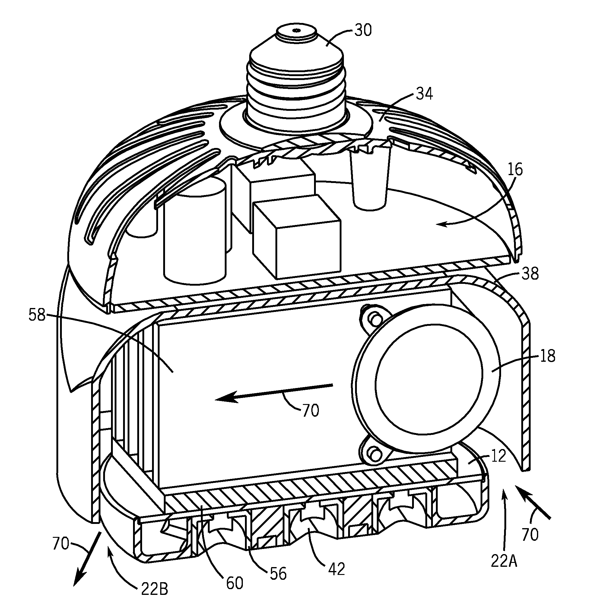
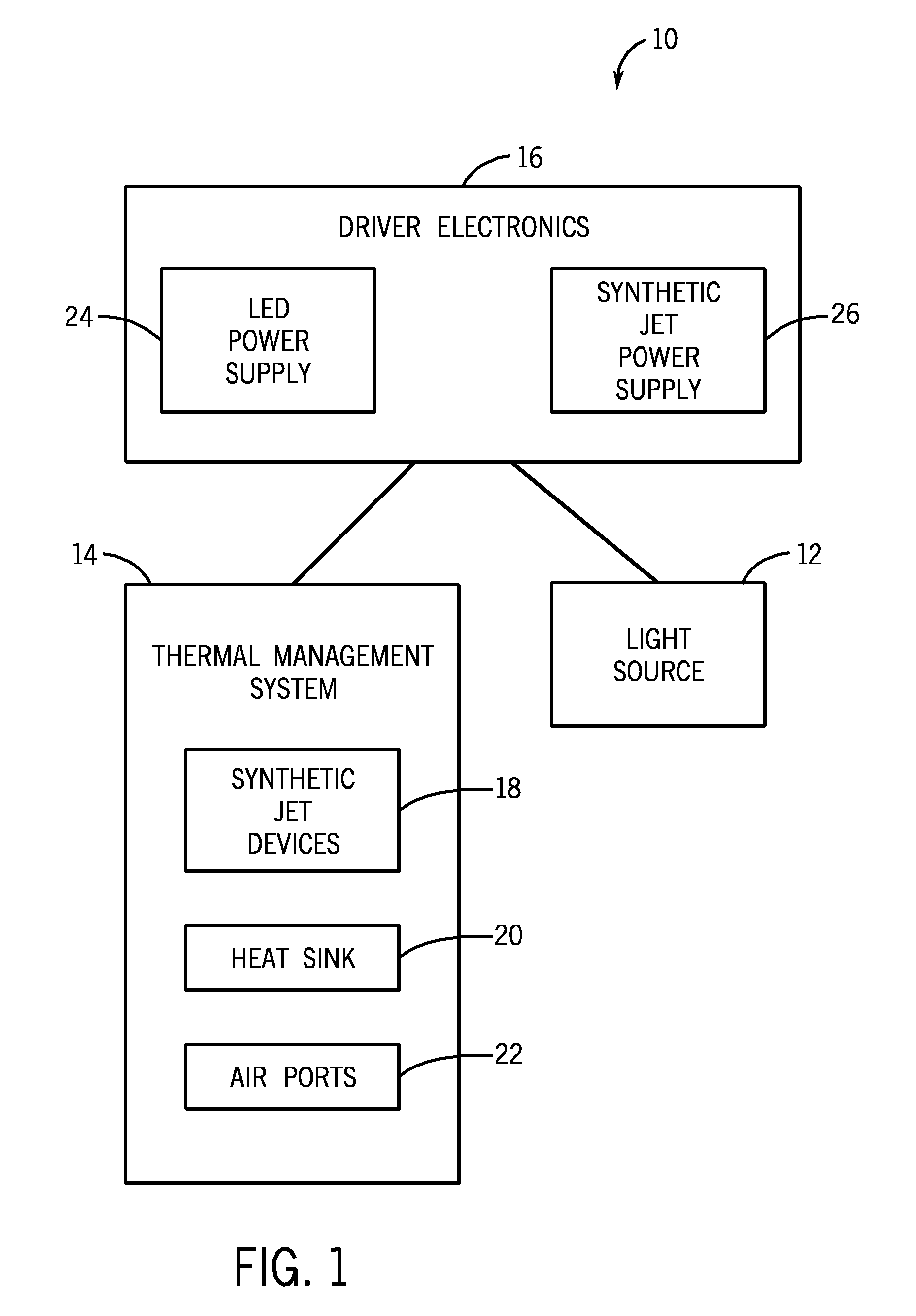
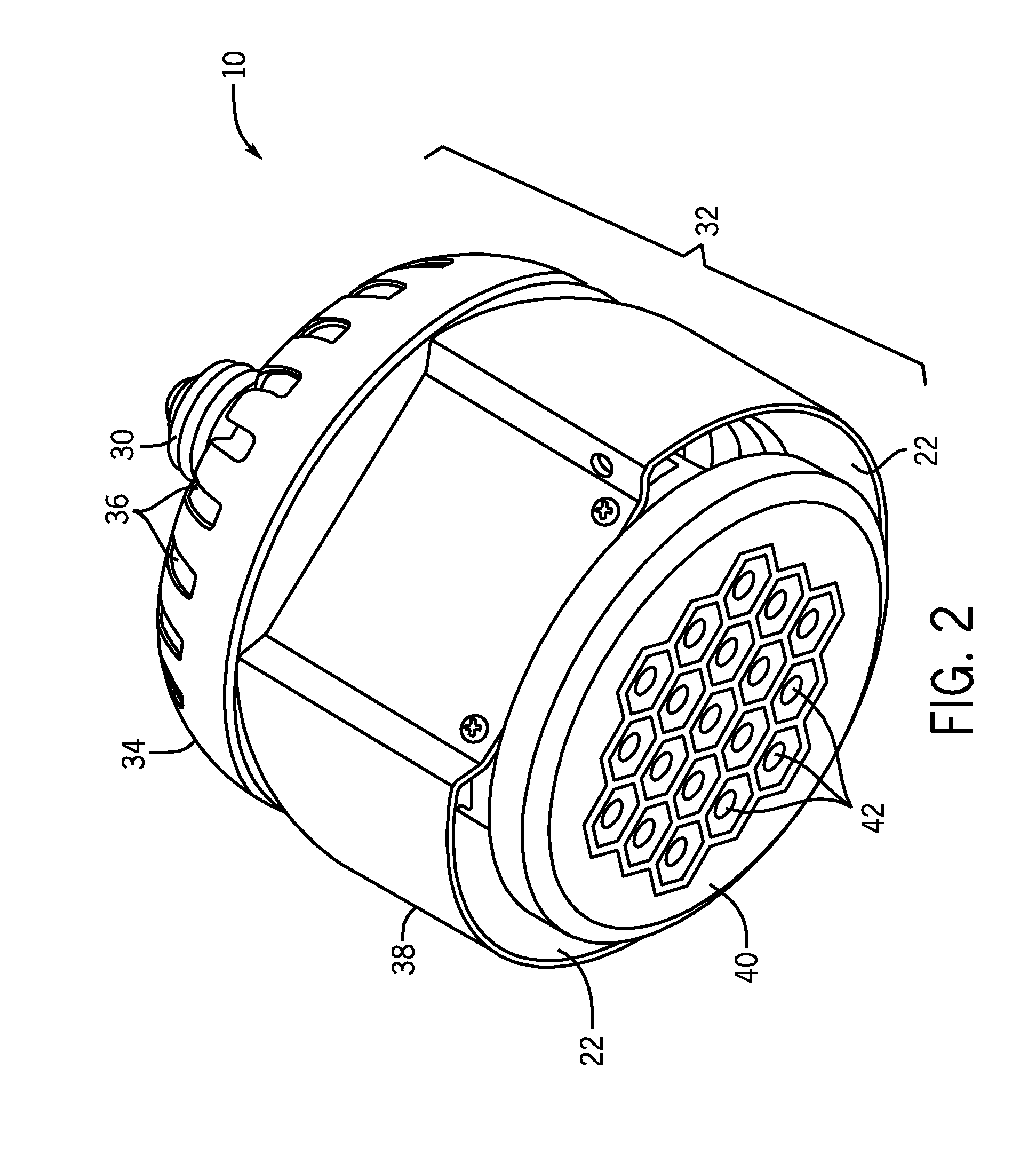
[0018]Embodiments of the invention generally relate to LED-based area lighting systems. A novel luminaire is provided with driver electronics, LED light source and an active cooling system, which includes synthetic jets. In one embodiment, the lighting system fits into a standard 6″ (15.2 cm) halo and leaves approximately 0.5″ (1.3 cm) between the lamp and halo. Alternatively, the lighting system may be scaled differently, depending on the application. The presently described embodiments provide a lighting source, which produces approximately 1500 lumens (lm) with a driver electronics efficiency of 90%, and may be useful in area lighting applications. The thermal management system includes synthetic jet cooling which provides an air flow in and out of the lighting system, allowing LED junction temperatures to remain less than 100° C. for the disclosed embodiments. To reach 1500 lm, the disclosed light source utilizes blue LEDs and a phosphor mixture that results in a correlated colo...


PUM


Abstract

Lighting systems having unique configurations are provided. For instance, the lighting system may include a light source, a thermal management system and driver electronics, each contained within a housing structure. The light source is configured to provide illumination visible through an opening in the housing structure. The thermal management system is configured to provide an air flow, such as a unidirectional air flow, through the housing structure in order to cool the light source. The driver electronics are configured to provide power to each of the light source and the thermal management system.

Description

STATEMENT REGARDING FEDERALLY SPONSORED RESEARCH & DEVELOPMENT[0001]This invention was made with Government support under contract number DE-FC26-08NT01579 awarded by The United States Department of Energy. The Government has certain rights in the invention.BACKGROUND OF THE INVENTION[0002]The invention relates generally to lighting systems, and more particularly to lighting systems having thermal systems.[0003]High efficiency lighting systems are continually being developed to compete with traditional area lighting sources, such as incandescent or florescent lighting. While light emitting diodes (LEDs) have traditionally been implemented in signage applications, advances in LED technology have fueled interest in using such technology in general area lighting applications. LEDs and organic LEDs are solid-state semiconductor devices that convert electrical energy into light. While LEDs implement inorganic semiconductor layers to convert electrical energy into light, organic LEDs (OLE...

Claims


Application Information

Patent Timeline
IPC IPC(8): H01J13/32H01J61/52H05B44/00
CPCF21V29/02F21V29/2293H05B33/0803F21V29/405F21K9/1375F21V23/006F21Y2105/001F21K9/135F21V29/004H01L2924/0002F21Y2101/02F21V29/225F28F3/02F21V29/002F21V29/63F21V29/74F21V29/763F21V29/83F21V29/2206H01L2924/00F21Y2105/10F21K9/23F21K9/232F21Y2115/10F21K9/238H05B45/36H05B45/385H05B45/31
Inventor ARIK, MEHMETWEAVER, STANTONSTECHER, THOMASSEELEY, CHARLESKUENZLER, GLENNWOLFE, JR., CHARLESUTTURKAR, YOGENSHARMA, RAJDEEPPRABHAKARAN, SATISHICOZ, TUNC
Owner SAVANT TECH LLC
Why Eureka
Try Eureka