


Quick Research
Generate reliable direction feasibility study reports for your R&D in just a few steps.

Technical Q&A
Discover and master advanced knowledge NOW. Basics, ideas, possibilities, all at once.

Find Solutions
As an expert in R&D theories, this can generate solutions to your technical problems instantly.

Evaluate Feasibility
Analyze your overall solution with one click, know your potential R&D risks in advance.

Monitor Landscape
Get weekly tech updates, stay abreast of the latest tech innovations and key insights.
Liquid droplet discharging apparatus, liquid discharging method, color filter producing method, and organic el device producing method
一种制造方法、液滴的技术,应用在对表面涂布液体的装置、半导体/固态器件制造、滤光片等方向,能够解决喷出状态差、喷出不均等问题
- Summary
- Abstract
- Description
- Claims
- Application Information
AI Technical Summary
Problems solved by technology
Method used
Image

Examples
Embodiment approach 1
[0055]
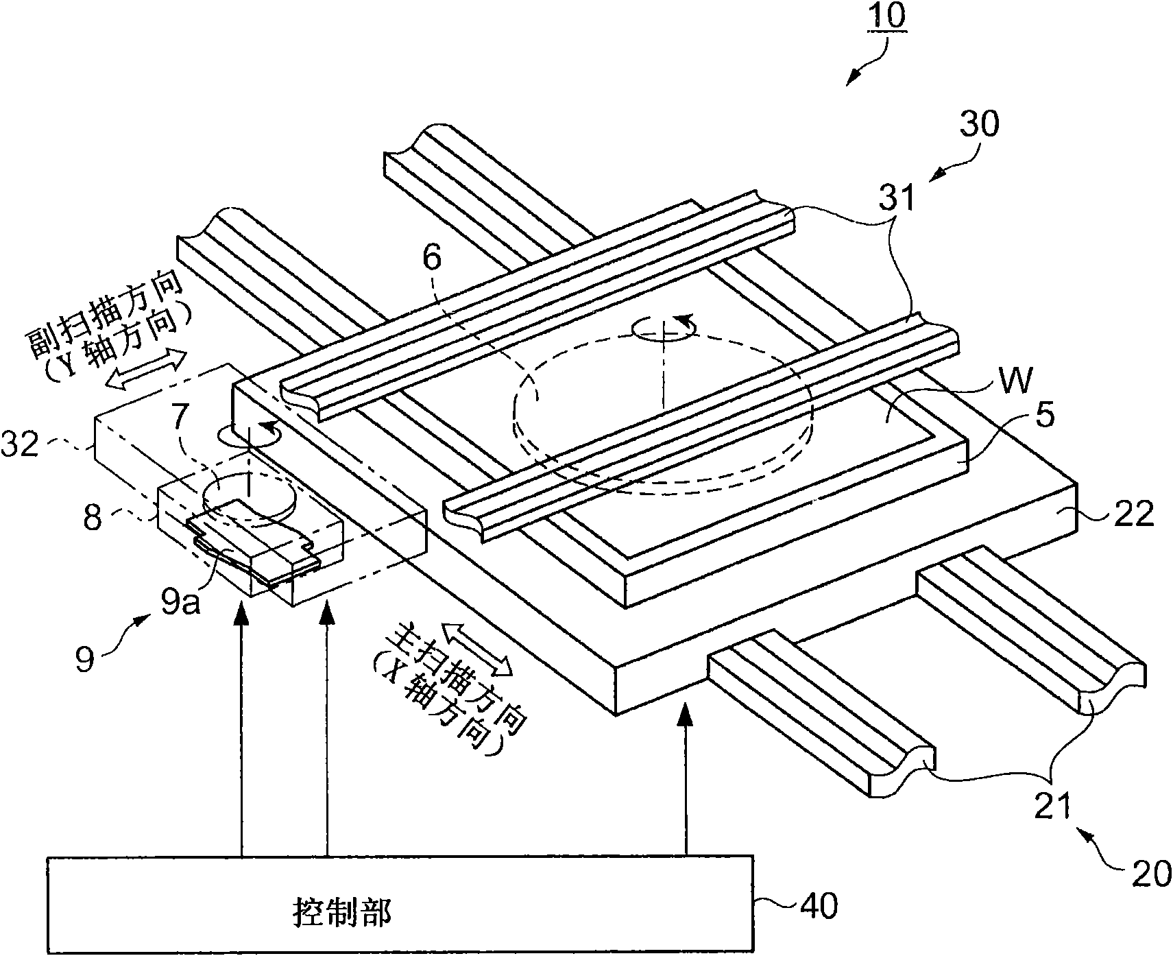
[0056] First of all, refer to Figure 1 ~ Figure 6 A description will be given of the droplet ejection device of this embodiment. figure 1 It is a schematic perspective view showing the structure of a droplet ejection device.
[0057] Such as figure 1 As shown, the droplet ejection device 10 includes: a workpiece moving mechanism 20 as a first moving mechanism that moves the workpiece W in the main scanning direction (X-axis direction) as the first direction; The head moving mechanism 30 as the second moving mechanism moves in the sub-scanning direction (Y-axis direction) which is the second direction orthogonal to the direction.
[0058] The workpiece moving mechanism 20 includes a pair of guide rails 21, a moving table 22 that moves along the pair of guide rails 21, and a stage 5 on which a workpiece W arranged on the moving table 22 via a rotating mechanism 6 is placed.
[0059] The moving table 22 uses an air piston and a linear motor (not shown) provided inside the...
Embodiment approach 2
[0145]
[0146] Refer to Picture 12 and Figure 13 A description will be given of a method of manufacturing an organic EL device to which the liquid ejection method of the first embodiment described above is applied. Picture 12 It is a schematic cross-sectional view showing the main structure of the organic EL device, Figure 13 (a) to (f) are schematic cross-sectional views showing a method of manufacturing an organic EL device.
[0147]
[0148] Such as Picture 12 As shown, the organic EL device 600 of this embodiment includes an element substrate 601 having a light-emitting element portion 603 as an organic EL element, and a sealing substrate 620 sealed with the element substrate 601 and a space 622 interposed therebetween. In addition, the element substrate 601 includes a circuit element portion 602 on the element substrate 601, and the light emitting element portion 603 is formed by overlapping the circuit element portion 602 and is driven by the circuit element portion ...
PUM
 Abstract
Description
Claims
Application Information
 - R&D Engineer
- R&D Manager
- IP Professional
- Industry Leading Data Capabilities
- Powerful AI technology
- Patent DNA Extraction
Browse by: Latest US Patents, China's latest patents, Technical Efficacy Thesaurus, Application Domain, Technology Topic, Popular Technical Reports.
© 2024 PatSnap. All rights reserved.Legal|Privacy policy|Modern Slavery Act Transparency Statement|Sitemap|About US| Contact US: help@patsnap.com