Automobile rear floor frame assembly

A rear floor and assembly technology, applied to upper structure sub-assembly, vehicle components, upper structure, etc., to achieve the effects of reducing maintenance costs, improving torsional rigidity, and mature and stable technology

Inactive Publication Date: 2010-12-22
CHONGQING CHANGAN AUTOMOBILE CO LTD
View PDF0 Cites 0 Cited by
  • Summary
  • Abstract
  • Description
  • Claims
  • Application Information

AI Technical Summary

Problems solved by technology

[0002]Because during the rear collision process of the car, if the rigidity of the rear part of the body is too strong, the body cannot deform to absorb the huge impact energy and cause a huge impact to the occupants; if the body Because the rear part lacks the necessary rigidity and strength, a small slight impact will cause permanent damage to the body, causing unnecessary losses to consumers, and it is very likely to squeeze the fuel tank, causing great danger to the occupants
[0003] At present, the rear floor assembly structure of most models is "H" type, and the left and right side components are basically integral. Generally, to meet the needs of rear impact, the entire structure The strength is very high. When the rear impact energy is very strong, the energy will be directly transmitted to the cockpit due to the lack of energy-absorbing structure, and due to the lack of energy transmission channels due to the lack of beams, the occupants will bear greater impact. The energy transfer process and regional importance are different to meet the reasonable distribution intensity requirements, which can easily cause unnecessary damage to the body and danger to the lives of the occupants.

Method used


Image

  • Automobile rear floor frame assembly
  • Automobile rear floor frame assembly
  • Automobile rear floor frame assembly

Examples


Embodiment Construction

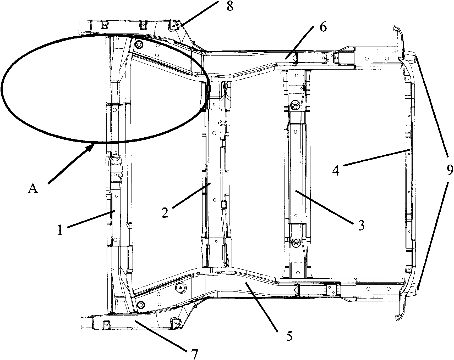
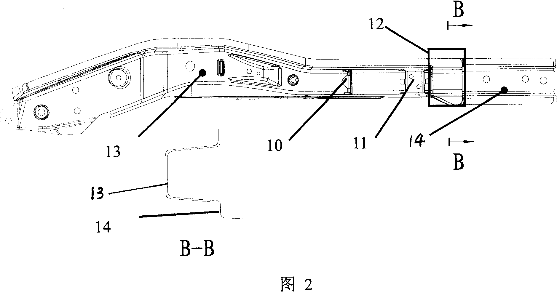
[0020] Both the left side of the rear floor side beam assembly and the right side of the rear floor side beam assembly adopt the form of welding combination of front and rear parts, such as figure 2 and figure 2 As shown in A, the front part 13 of the rear floor sill and the rear part 14 of the rear floor sill are welded at the region 12 by spot welding, and the welded regions are superimposed to form a buffer structure region 12 with a difference in thickness.

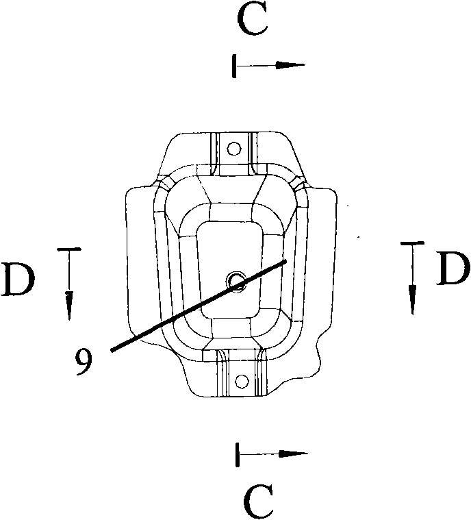
[0021] see image 3 , Figure 3A , Figure 3B , the rear end and the rear part and the rear skirt plate 4 joints are welded with a collision deformation box 9 at the rear end of the left side 5 of the back floor side beam assembly and the right side 6 of the back floor side beam assembly. F is the direction of force.

[0022] After adopting the structural design of the present invention, the main principle of the rear safety design of the vehicle body occurs in the following two situations when the vehicle colli...


PUM


Abstract

The invention provides an automobile rear floor frame assembly which comprises a left rear floor lower longitudinal beam assembly, a right rear floor lower longitudinal beam assembly, and rear floor lower transverse beam assemblies; the amount of the rear floor lower transverse beam assemblies is three, namely front rear floor lower transverse beam assembly, middle rear floor lower transverse beamassembly and back rear floor lower transverse beam assembly which are respectively welded at the front ends and middle parts of the left rear floor lower longitudinal beam assembly and the right rearfloor lower longitudinal beam assembly; a rear apron board assembly is welded at the rear ends of the left rear floor lower longitudinal beam assembly and the right rear floor lower longitudinal beamassembly; a left rear floor side beam assembly and a right rear floor side beam assembly are welded at the outer side of the front parts of the left rear floor lower longitudinal beam assembly and the right rear floor lower longitudinal beam assembly; and the seven parts are welded mutually so as to form a close type rear floor frame structure. When the vehicle is collided, if the impact energy is weak, the structure can ensure the vehicle body does not generate permanent deformation, thereby reducing the maintenance cost of the consumers; and when the impact energy is strong, the vehicle body deforms automatically, thus absorbing the energy, guaranteeing that the members does not suffer huge impact and ensuring that the fuel system is not heavily squeezed and damaged.

Description

technical field [0001] The invention relates to the passive safety structure design of the rear part of the vehicle body, in particular to the rear floor frame of the automobile. Background technique [0002] During the rear collision process of the car, if the rigidity of the rear part of the body is too strong, the body cannot deform to absorb the huge impact energy and cause a huge impact to the occupants; if the rear part of the car body lacks the necessary rigidity and strength, a small slight impact Just will cause the permanent damage of vehicle body, cause the unnecessary loss of consumer, and very likely extrude fuel tank, cause great danger to occupant. [0003] At present, the rear floor assembly structure of most models is "H" type, and the left and right side components are basically integral. Generally, to meet the needs of rear impact, the entire structure is very strong. When the energy of rear impact is very strong, due to the lack of The energy-absorbing ...

Claims


Application Information

Patent Timeline
Patent Type & Authority Patents(China)
IPC IPC(8): B62D25/20
Inventor 顾建明李可周启国
Owner CHONGQING CHANGAN AUTOMOBILE CO LTD
Why Eureka
Try Eureka