Ball valve

A ball valve and hemisphere technology, applied in the field of ball valves, to achieve the effects of long service life, convenient installation and maintenance, and easy switching.

Active Publication Date: 2010-10-13
JIANGSU SUYAN VALVE MASCH CO LTD
View PDF6 Cites 1 Cited by
  • Summary
  • Abstract
  • Description
  • Claims
  • Application Information

AI Technical Summary

Problems solved by technology

[0005]Aiming at the problems encountered in the use of existing ball valves

Method used


Image

  • Ball valve
  • Ball valve
  • Ball valve

Examples


Embodiment 1

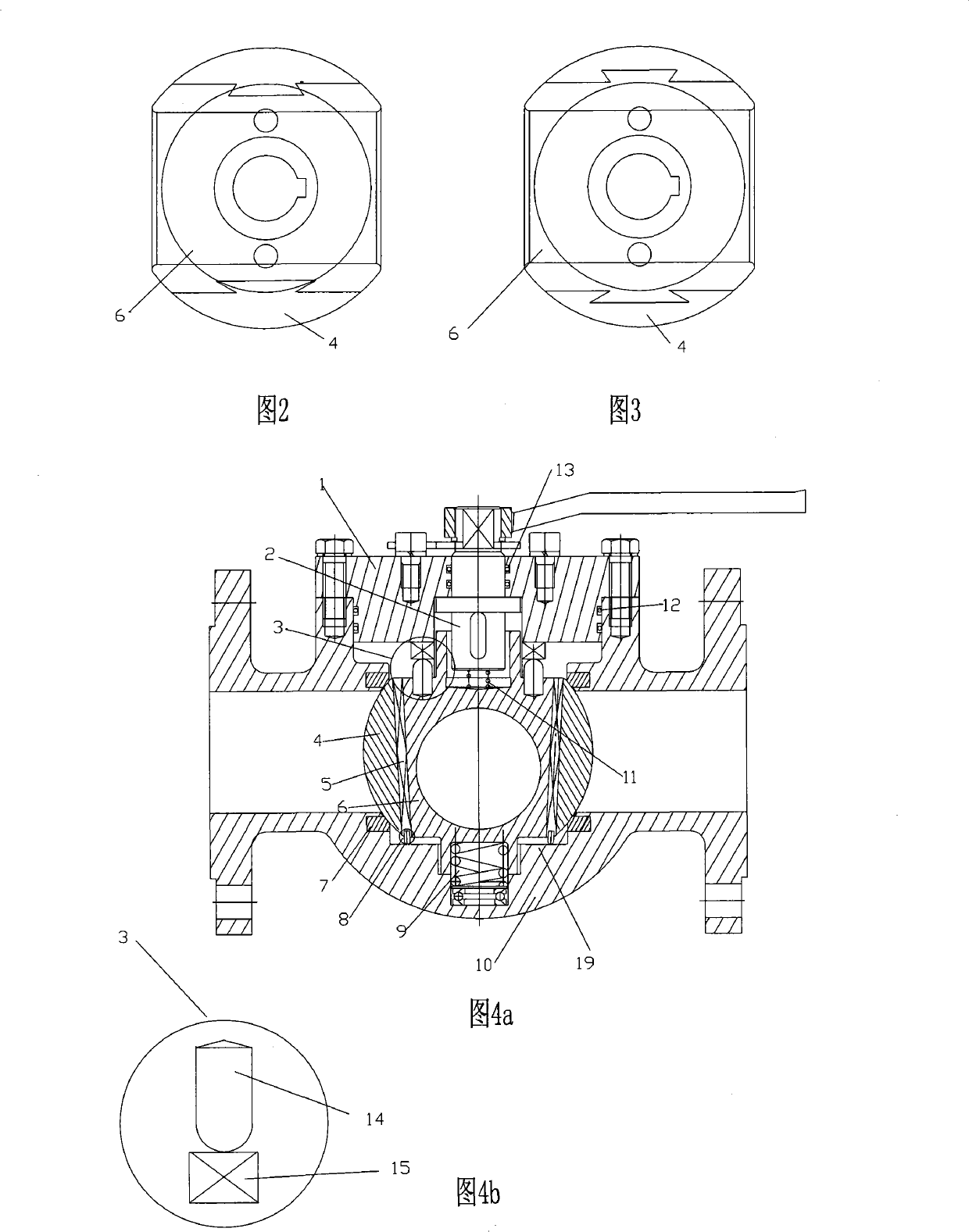
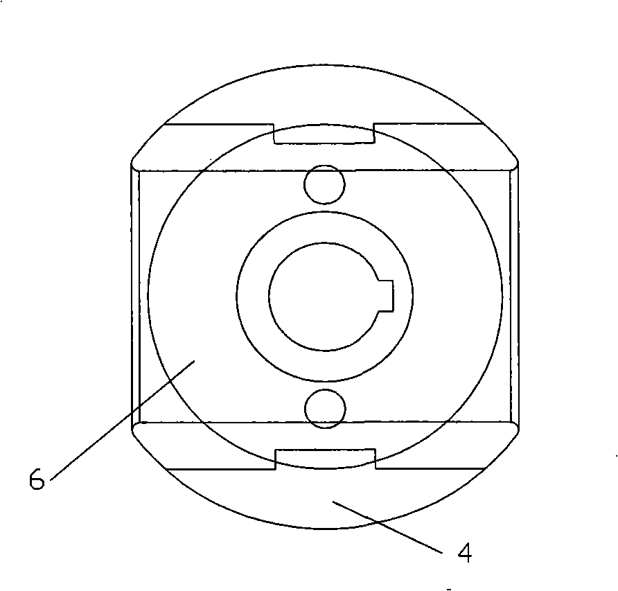
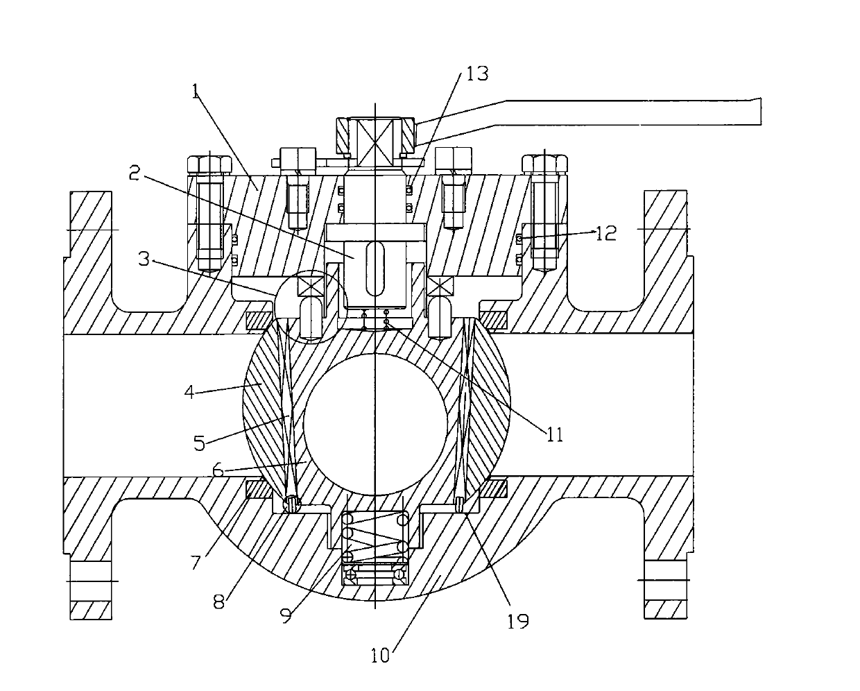
[0032] Such as Figure 1a , 1b , 2, 3 shown: the upper gland 1 is fixed on the valve body by bolts, and a sealing element 12 is installed between the upper gland 1 and the valve body to realize liquid sealing. The upper end of the rotary shaft 2 is connected to the handle, and the lower end passes through the upper gland 1 and is inserted into the hole at the upper end of the wedge-shaped ball core 6. The hole is an oblong hole, a square hole, a rectangular hole, and a circular hole with keys for fixing the positions of the two. Or other devices that can prevent the relative rotation of the two during rotation. The shaft head at the lower end of the rotary shaft 2 corresponds to the hole at the upper end of the wedge-shaped ball core 6, and a seal 13 is installed between the rotary shaft 2 and the upper gland 1 to realize a liquid seal.

[0033] A thrust mechanism 3 is installed between the lower end of the upper gland and the wedge-shaped spherical core. During the rotation...

Embodiment 2

[0038] Such as Figure 4a , 4b As shown: the thrust mechanism 3 is composed of a plane cam 15 and a movable plug 14, wherein the plane cam 15 is installed on the wedge-shaped ball core 6, and the movable plug 14 is installed on the lower surface of the upper gland 1. The head of the movable plug 14 abuts on the plane cam 15, and the wedge-shaped ball core 6 drives the movable plug 14 to move along the surface of the plane cam 15 when the wedge-shaped ball core 6 rotates. Driven by the thrust mechanism 3, the wedge-shaped ball core 6 can move up and down relative to the sealed hemisphere 4.

[0039] The loose plug 14 in Embodiments 1 and 2 can also be directly processed on the wedge-shaped ball core 6 or the lower surface of the upper gland 1 .

Embodiment 3

[0041] Such as Figure 5a , 5b As shown: the thrust mechanism 3 can also be made up of two plane cams 15, the upper plane cam 15 is installed on the lower surface of the upper gland 1, the lower plane cam 15 is installed on the top of the wedge-shaped ball core 6, and the two plane cams 15 surface in contact. When the rotary shaft 2 drives the wedge-shaped ball core 6 to rotate, the two planar cams 15 also rotate relatively. Driven by the two flat cams 15, the wedge-shaped ball core 6 can move up and down relative to the sealing hemisphere 4 .


PUM


Abstract

The invention relates to a ball valve, especially the ball valve with the split valve core. The valve body is equipped with the removable valve cover. The valve core installed in the valve body consists of two seal hemispheres and the wedge-shaped ball core installed between the seal hemispheres. The relative position between the seal hemispheres and the wedge-shaped ball core is determined by theanti-rotation guiding device. The top of the wedge-shaped valve core has the anti-rotation device and the thrust block is installed between the valve cover and the wedge-shaped ball core. The elasticunit is installed between the bottom of wedge-shaped ball core and the valve seat. The ball valve features easy switch; small ball valve wear, long service life; convenient installation and maintenance, etc., which can be applied to a wide range of area.

Description

technical field [0001] The invention relates to a ball valve. Background technique [0002] Pipelines are usually used to transport media in industrial or civil infrastructure, where the pipeline is regulated due to changes in pressure or temperature. In order to adjust the flow, an adjustment mechanism, especially a ball valve, is used in the pipeline to ensure the best Working conditions and environmental safety. [0003] Ball valves usually use a sphere with a circular passage as the opening and closing element, and the sphere realizes the opening and closing action with the rotation of the valve body. The opening and closing part of the ball valve is a ball with a through hole, which rotates around the axis perpendicular to the channel, so as to achieve the purpose of opening and closing the channel. A traditional ball valve is usually a sphere with a through hole installed on the valve seat, and the opening and closing are realized by the rotation of the sphere. Bal...

Claims


Application Information

Patent Timeline
Patent Type & Authority Patents(China)
IPC IPC(8): F16K5/06F16K1/14F16K1/32F16K1/50F16K31/60
Inventor 胡金木
Owner JIANGSU SUYAN VALVE MASCH CO LTD
Why Eureka
Try Eureka