Optical symbol, article to which the optical symbol is attached, method for attaching optical symbol to article, optical symbol decoding method, related device, and related program

A symbol and optical technology, applied in the field of optical codes, can solve problems such as difficulty in use and pattern

Active Publication Date: 2009-10-07
B CORE INC
View PDF12 Cites 8 Cited by
  • Summary
  • Abstract
  • Description
  • Claims
  • Application Information

AI Technical Summary

Problems solved by technology

[0096] (1) In addition, in the case of 1D color bit code, it is a code based on a combination of a plurality of types (for example, three types) of colors, so it is very difficult to form a unique pattern without extreme redundancy.
However, the extreme verbosity involves growing the color column, so its use is difficult as a practical matter

Method used


Image

  • Optical symbol, article to which the optical symbol is attached, method for attaching optical symbol to article, optical symbol decoding method, related device, and related program
  • Optical symbol, article to which the optical symbol is attached, method for attaching optical symbol to article, optical symbol decoding method, related device, and related program
  • Optical symbol, article to which the optical symbol is attached, method for attaching optical symbol to article, optical symbol decoding method, related device, and related program

Examples


Embodiment approach 1

[0266] Below, according to the attached Figure 1-13 Preferred embodiments of the present invention will be described.

[0267] In this embodiment, it is proposed to use an optical symbol code having linearly arranged cells. This optical symbol is a flat symbol and is attached to various items.

[0268] Unit (structural unit) and end unit

[0269] The optical symbol of this embodiment is composed of cells and endpoint cells. The so-called cell is a range / area where one color is added, and various shapes can be obtained. A circle or a square, a triangle, etc. may be used. Optical symbols are formed by arranging the cells in a line.

[0270] In addition, an end point cell is a cell located at an end point of an optical symbol formed by a group of cells connected in a line. In this embodiment, an end point cell is an area / range that is colored differently from cells other than the end point cell. In addition, as will be described later, it is possible to indicate whether...

Embodiment 1-1

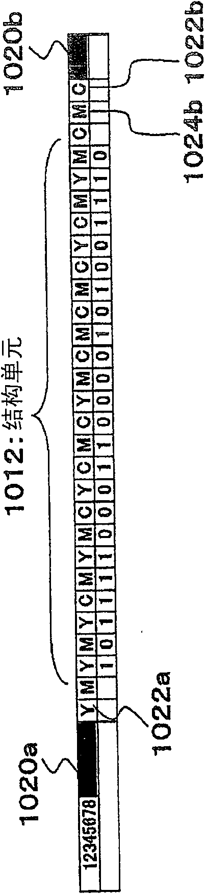
[0276] exist figure 1 In , an example of an optical symbol 10 representing a numerical value "12345678" (decimal number) is shown. In this embodiment 1-1, 12345678 is marked as "101111000110000101001110" by the binary method, so in this embodiment 1-1, the binary number is expressed as "101111000110000101001110".

[0277] exist figure 1 In , a square with Y (indicates yellow), M (indicates magenta), C (indicates cyan), etc. is a cell 1012 . A plurality of such units 1012 are connected to form an optical symbol 1010 .

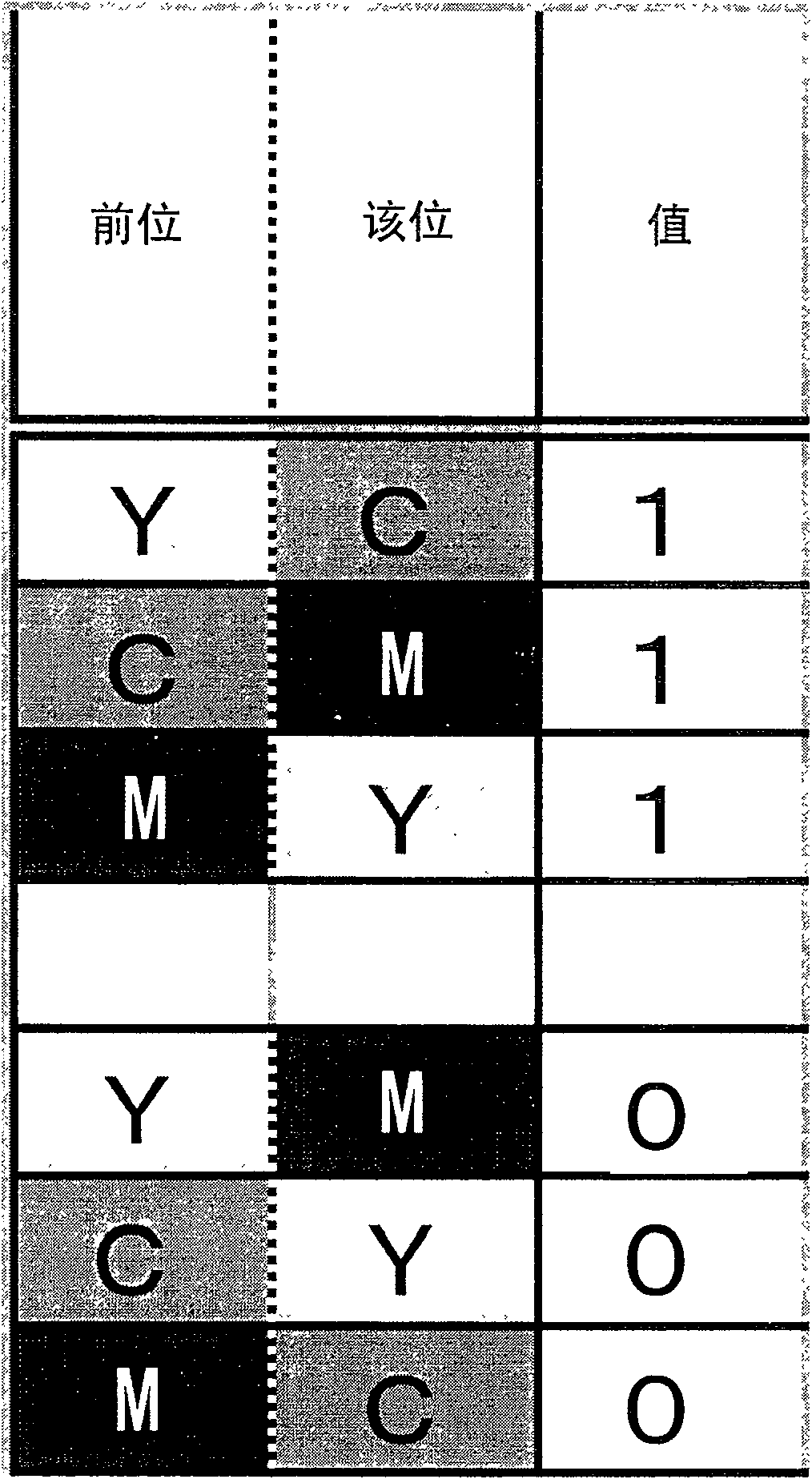
[0278] Also, in the present embodiment 1-1, the constituent elements "0" and "1" of the binary number are as follows figure 2 as indicated in the table. That is, instead of assigning "1" and "0" to the color, "1" and "0" are assigned to the transition of the color. In the first example of this embodiment, black, cyan (C), magenta (M), and yellow (Y) are used, and the color transitions from Y to C, from C to M, and from M to Y represent "1" ( refer to ...

Embodiment 1-2

[0299] Image 6 Indicates an example of encoding numbers, letters, etc. directly (directly without converting them into binary numbers temporarily). exist Image 6 In , three conversion tables representing how each number or letter is converted are expressed. The three types indicate three types prepared for switching from C, switching from M, and switching from Y in accordance with the color of the first cell 1012 .

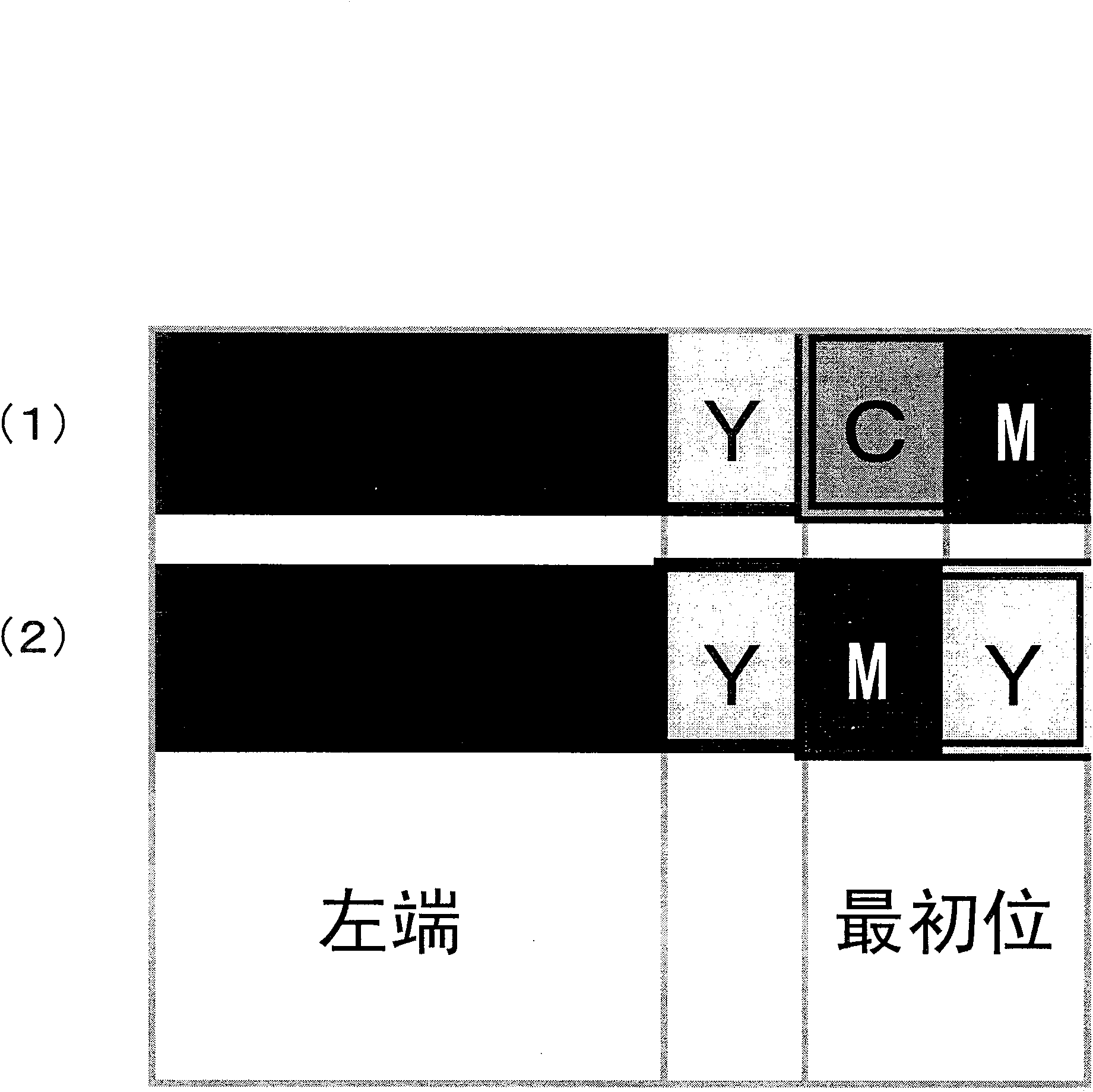
[0300] That is, in order to represent "0", there are three representation methods of arranging the cells 1012 in the order of "YMYCM", arranging the cells 1012 in the order of "MCMYC", and arranging the cells 1012 in the order of "CYCMY". To match the color of the previous unit 1012, select any one of the three.

[0301] and, Image 6 By the method shown in the present embodiment 1-2, the code system is defined according to the direction in which the colors of adjacent cells 1012 change. exist Figure 7 In , explanatory diagrams showing the relationship of...


PUM


Abstract

It is possible to linearly arrange cells and indicate particular data in the order of colors of respective sells. A code system uses an optical symbol decoding method capable of reading the color arrangement if the arrangement continuity and the linear shape are maintained. The data expression method may be other than 'the order of colors'. For example, it is possible to employ a method for allocating a numeric value to each of the colors by one-to-one correspondence (R - 0, B = 1, etc.), a method for allocating data by a color transition ('CM' = 'MY' = 'YC' = 0, 'CY' = 'YM' = 'MC' = 1, etc.), a method for allocating data for a combination of colors, and the like.

Description

technical field [0001] The present invention relates to adding optical codes for information processing to articles. In particular, it relates to an optical symbol used by the optical code, a method of attaching the optical symbol to an article, and a decoding method. [0002] The invention also relates to optical identification codes. In particular, it relates to the reading technology of the optical identification code (symbol interception technology). [0003] Furthermore, it relates to an optical identification code, and particularly relates to an efficient data restoration method for an optical identification code called 1D color bit code (Japanese Patent Application No. 2006-196705) proposed by the present inventor. Furthermore, methods suitable for efficient data restoration are also proposed. That is, the present invention also relates to the encoding technology of the optical identification code. Background technique [0004] "Background Technology One" [0005...

Claims


Application Information

Patent Timeline
Patent Type & Authority Applications(China)
IPC IPC(8): G06K19/06G06K7/12
Inventor 木村昭辉松田昌幸汉人邦夫
Owner B CORE INC
Why Eureka
Try Eureka