Inertia variable engine

An engine and variable technology, applied in the direction of engine control, machine/engine, mechanical equipment, etc., can solve the problems of economical decline, increased engine fuel consumption, etc., and achieve good environmental performance, fuel saving, and reliable work.

Active Publication Date: 2012-12-19
张家港市乐余科创园投资发展有限公司
View PDF6 Cites 0 Cited by
  • Summary
  • Abstract
  • Description
  • Claims
  • Application Information

AI Technical Summary

Problems solved by technology

Therefore, in order to be able to run stably without stalling when the traditional engine is idling, it is necessary to increase its idle speed, which will virtually increase the fuel consumption of the engine and reduce the economy.

Method used


Image

  • Inertia variable engine
  • Inertia variable engine
  • Inertia variable engine

Examples


Embodiment Construction

[0010] Figure number

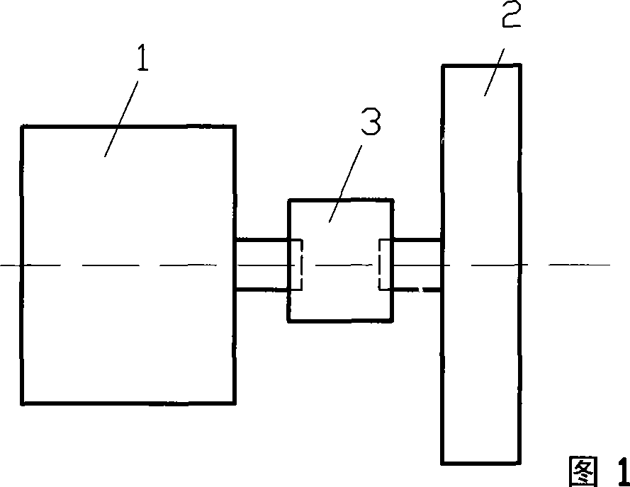
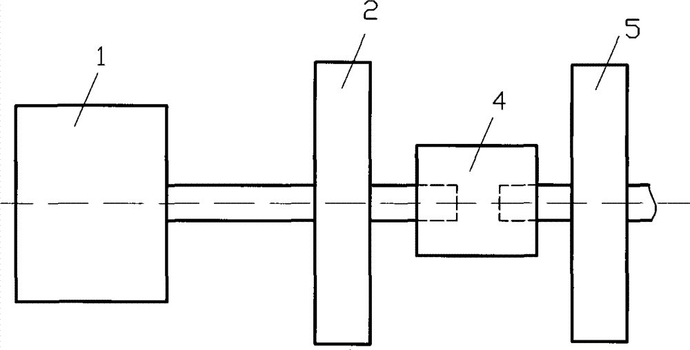
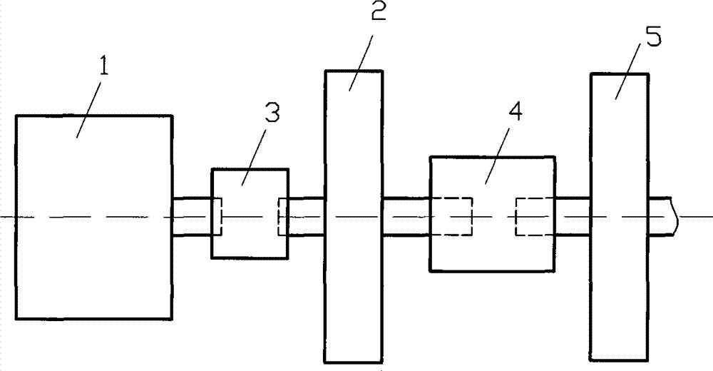
[0011] 1. Engine 2. Flywheel 3. Transmission

[0012] 4. Clutch device 5. Inertia body

[0013] The present invention is described in detail below in conjunction with accompanying drawing and specific embodiment:

[0014] Please refer to figure 1 The variable inertia engine shown includes: an engine 1 and a flywheel 2, the crankshaft of the engine 1 is fixedly connected to the flywheel 2 via a speed change device 3, and the control device of the speed change device 3 is linked with the throttle of the engine.

[0015] Please refer to figure 2 As shown in the variable inertia engine, the crankshaft of the engine 1 is directly connected to the flywheel 2, and the flywheel 2 is connected to the inertia body 5 through a mechanical or electromagnetic clutch device 4, and the mechanical or electromagnetic clutch device The control device of 4 is linked with the accelerator of engine.

[0016] Please refer to image 3 As shown in the variable inertia eng...


PUM


Abstract

The invention discloses an inertia variable engine. The inertia variable engine comprises an engine and a flywheel. A crankshaft of the engine is fixedly connected with the flywheel directly or by a variable speed gear, the flywheel is connected with an inertia body by a mechanical engaging and disengaging gear or an electromagnetic engaging and disengaging gear, the inertia body is a rotary structure with a certain inertia, and the variable speed gear or a control device of the mechanical engaging and disengaging gear or the electromagnetic engaging and disengaging gear is linked with an engine throttle. Idle speed of the engine is reduced by changing moment of inertia of the engine flywheel. The inertia variable engine has simple structure, reliable operation and good environmental protection performance and saves fuel.

Description

technical field [0001] The invention relates to the field of engines. Background technique [0002] The "idling speed" of the engine refers to the minimum speed at which the engine is not connected to the external load and only maintains the normal operation of the engine without external work. When the engine maintains its own operation at a lower speed, it generally only needs the engine to emit less than 10% of the usual rated power, and the speed is about 20% of the rated speed. At this time, the speed and combustion volume of the engine are not in the best state in the original design of the engine, the state of fuel supply and ignition is on the verge of being stable and stopped, and the flywheel of the engine does not have enough inertia at this time. A little bit of air leakage, lack of oil, misfire or load change can no longer maintain this low-speed operation. Therefore, in order to be able to operate stably without stalling when the traditional engine is idling,...

Claims


Application Information

Patent Timeline
Patent Type & Authority Patents(China)
IPC IPC(8): F02D1/04
Inventor 靳北彪
Owner 张家港市乐余科创园投资发展有限公司
Why Eureka
Try Eureka