Hydraulically based continuously variable inertial capacity

A variable, inertial-capacity technology, used in transmissions, friction transmissions, flywheels, etc., can solve problems such as inability to adjust inertia, and achieve the effect of a wide range of applications

Active Publication Date: 2021-09-03
NANJING UNIV OF SCI & TECH
View PDF0 Cites 0 Cited by
  • Summary
  • Abstract
  • Description
  • Claims
  • Application Information

AI Technical Summary

Problems solved by technology

[0007] The purpose of the present invention is to provide a continuously variable inertial capacity based on hydraulic pressure, which solves the problem that most of the existing inertial capacity has fixed inertia, cannot adjust the inertia in real time during work, and can only be used as a passive component

Method used


Image

  • Hydraulically based continuously variable inertial capacity
  • Hydraulically based continuously variable inertial capacity
  • Hydraulically based continuously variable inertial capacity

Examples


Embodiment Construction

[0018] The present invention will be described in further detail below in conjunction with the accompanying drawings.

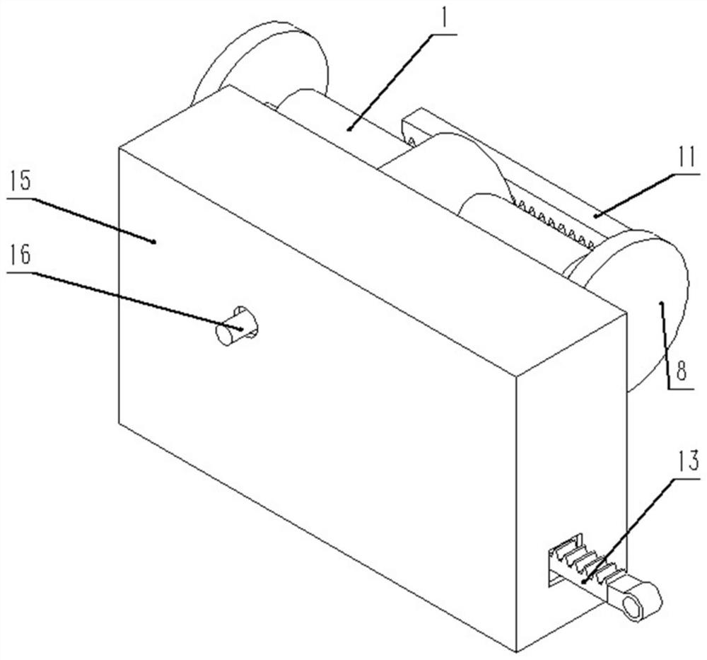
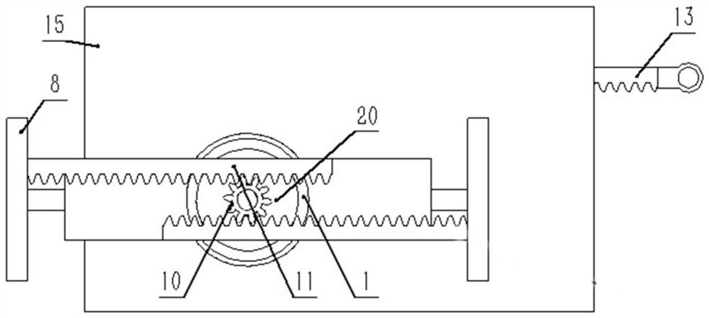
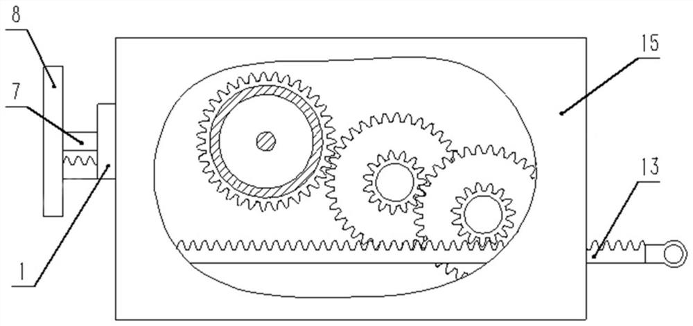
[0019] to combine Figure 1 to Figure 6 , the hydraulic-based continuously variable inertial capacity described in the present invention includes a flywheel assembly, a first rack and pinion mechanism, a second rack and pinion mechanism and a housing 15, and the flywheel assembly includes a T-shaped flywheel tube 1, a first piston assembly and two second piston assemblies, the T-shaped flywheel tube 1 includes a first round tube and two second round tubes, the bottom of the first round tube has an end cap, and the two second round tubes are symmetrically arranged at the bottom of the first round tube The two sides of the outer wall of the T-shaped flywheel jointly constitute a T-shaped flywheel tube 1. One end of the two second piston assemblies extends into the second circular pipe, the other end extends into the second circular pipe, and one end of the firs...


PUM


Abstract

The invention discloses a continuously variable inertial capacity based on hydraulic pressure, which includes a flywheel assembly, a first rack and pinion mechanism, a second rack and pinion mechanism and a housing. The flywheel assembly includes a T-shaped flywheel tube, a first piston assembly and two A second piston assembly, two second circular tubes are symmetrically arranged in the T-shaped flywheel tube with respect to the central symmetry axis of the T-shaped flywheel tube, and one end extends out of the T-shaped flywheel tube, and one end of the first piston assembly is arranged on the T-shaped flywheel tube. Inside the third tube, and one end protrudes from the third tube; the center of the bottom surface of the third tube of the T-shaped flywheel tube is provided with a bearing, the second rack and pinion mechanism is connected with the above-mentioned bearing, the first rack and pinion mechanism is connected with the first circle The pipes are connected, and the first rack and pinion mechanism is located in the casing, and the T-shaped flywheel pipe between the first piston assembly and the two second piston assemblies is filled with hydraulic oil. The invention solves the problem that most of the existing inertial capacity has fixed inertia, and the inertia cannot be adjusted in real time during work, and can only be used as a passive passive component.

Description

technical field [0001] The invention belongs to an energy storage element, in particular to a continuously variable inertial capacity based on hydraulic pressure. Background technique [0002] Inertia is a double-terminal mechanical energy storage device. The force applied at its two terminals with equal magnitude and opposite direction is proportional to the relative acceleration between the terminals. The proportional coefficient is called inertia. Inertia consists of a transmission structure and an inertial mechanism that converts translational motion into rotational motion, storing and releasing energy from its two terminals. [0003] In traditional engineering applications, there is an analogy between mechanical and electrical systems, the "force-current" analogy. In this analogy, the forces and relative velocities of a mechanical network are analogous to the currents and relative voltages of a circuit. In this way, the physical properties of inertia, damping, and spr...

Claims


Application Information

Patent Timeline
Patent Type & Authority Patents(China)
IPC IPC(8): F16H19/04F16F15/30
Inventor 陈志强刘元策张海中
Owner NANJING UNIV OF SCI & TECH
Why Eureka
Try Eureka