
Intake duct for vehicle

A technology for air intake pipes and vehicles, applied in the direction of fuel air intake, combustion air/combustion-air treatment, engine components, etc., can solve the problems of reducing the ventilation performance of the intake pipe and hindering smooth ventilation, etc. Effect of suppressing deflection and improving impact absorption capacity

Active Publication Date: 2009-10-14
INOAC CORP
View PDF1 Cites 6 Cited by
  • Summary
  • Abstract
  • Description
  • Claims
  • Application Information

AI Technical Summary

Problems solved by technology

Both of these conditions prevent smooth ventilation and reduce the ventilation performance of the intake duct

Method used


Image

  • Intake duct for vehicle
  • Intake duct for vehicle
  • Intake duct for vehicle

Examples


Embodiment Construction

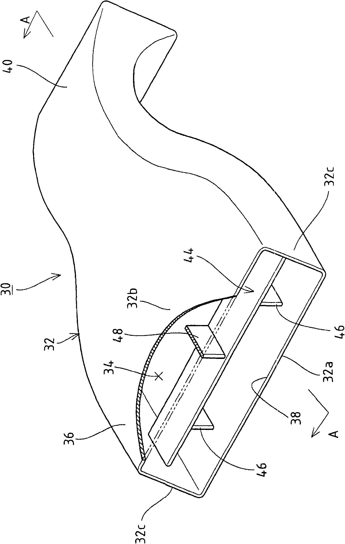
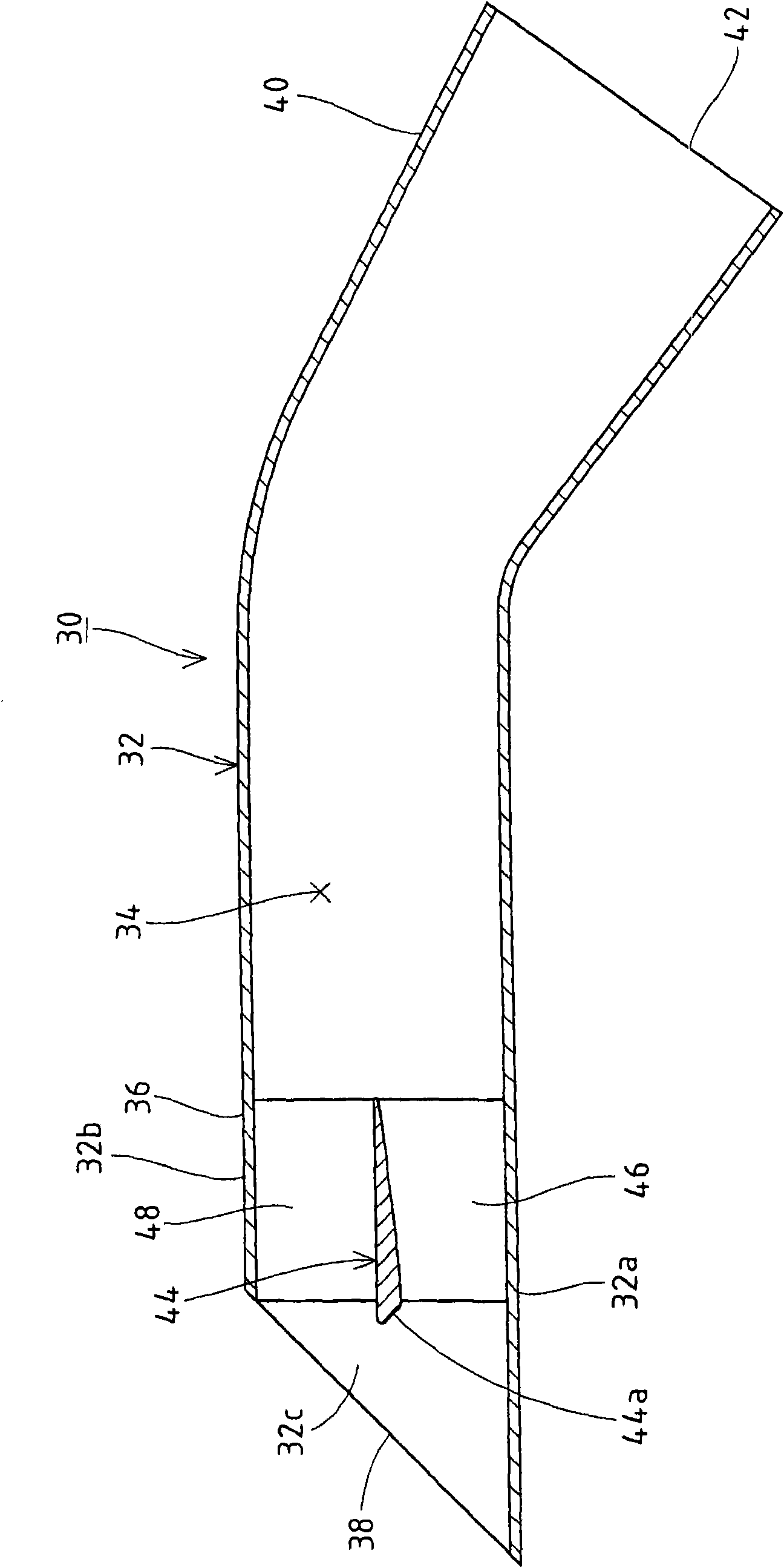
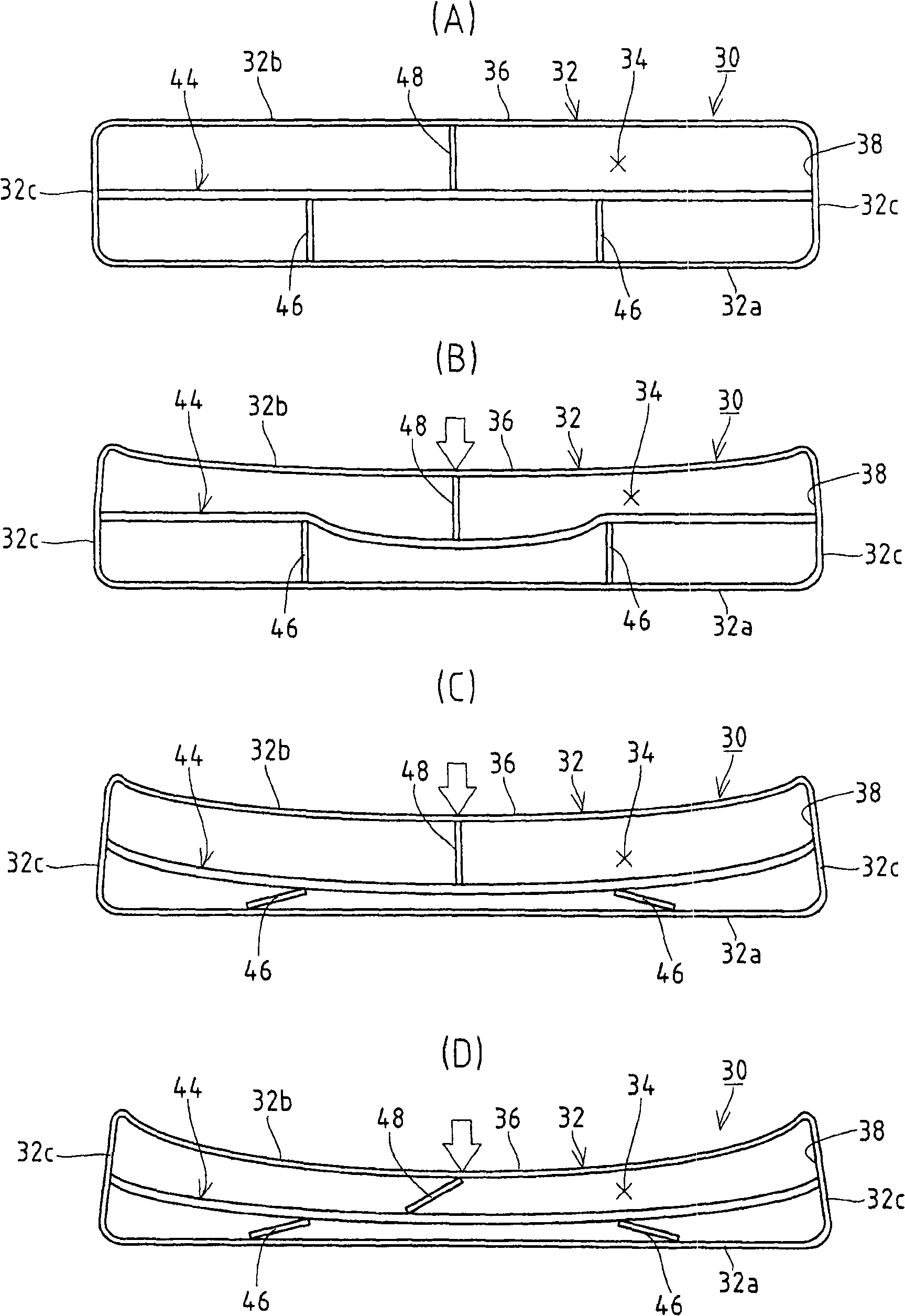
[0020] Preferred embodiments of an air intake duct for a vehicle according to the present invention will be described below with reference to the accompanying drawings. For convenience of description, the same reference numerals are given to those parts that are the same as the corresponding vehicle parts shown in FIG. 7 . In the following description of the vehicular air intake duct of the present invention, the reference direction is the direction in which air flows from the air inlet to the air outlet in the airflow channel defined in the vehicular air intake duct. The upstream side (air intake side) of the airflow direction in the vehicle air intake duct is called the "front side", and the downstream side (air outlet side) of the airflow direction is called the "rear side". In addition, the lateral direction perpendicular to the airflow direction of the vehicle intake pipe installed in the vehicle body is referred to as the left-right direction.

[0021] Such as figure 1...


PUM


Abstract

An intake duct for a vehicle having an inlet port formed so that the open side faces obliquely upward. The intake duct includes an inlet part formed in a flat shape expanding in the lateral direction crossing an air stream direction and a deflector provided in an air stream passage of the inlet part and extending in the left-and-right direction of the air stream passage. The intake duct further includes a first support member, which is provided between the deflector and the lower wall portion of the inlet part, and a second support member, which is provided between the deflector and the upperwall portion of the inlet part.

Description

technical field [0001] The invention relates to an air intake duct for a vehicle which supplies air to an engine. Background technique [0002] As shown in FIG. 7, in a vehicle, external air taken in through a vehicle intake duct DC is supplied to an engine EG through an air cleaner AC (see Japanese Patent Application Laid-Open No. 2006-322434). The vehicular intake duct DC is manufactured by injection casting or blow molding of synthetic resin, and has an air flow passage 20 defined therein. As shown in FIG. 8, the intake duct DC for a vehicle has an inlet portion 22 having an intake port 24 formed in a laterally elongated flat shape. The outlet portion 26 has an air outlet 28 connected to the air cleaner AC, and is formed in a substantially rectangular shape. In addition, the vehicle intake duct DC is bent between the inlet portion 22 and the outlet portion 26 at the middle portion. As shown in FIG. 7, the inlet portion 22 of the intake duct DC is attached to the top su...

Claims


Application Information

Patent Timeline
Patent Type & Authority Applications(China)
IPC IPC(8): F02M35/10
CPCF02M35/161F02M35/10013F02M35/10124
Inventor 木泽进一牧原真也保坂考一
Owner INOAC CORP
Learn More