Connecting device for flexible gas tube

A technology for connecting devices and gas pipes, which is applied in the directions of hose connecting devices, pipes/pipe joints/pipes, mechanical equipment, etc., can solve the problems of troublesome connection of flexible gas pipes, etc., and achieve the effect of easy connection

Active Publication Date: 2009-10-21
KOYO SANGYO CO LTD
View PDF1 Cites 2 Cited by
  • Summary
  • Abstract
  • Description
  • Claims
  • Application Information

AI Technical Summary

Problems solved by technology

Therefore, there is a problem that the connection of the flexible gas pipe is troublesome

Method used


Image

  • Connecting device for flexible gas tube
  • Connecting device for flexible gas tube
  • Connecting device for flexible gas tube

Examples


Embodiment Construction

[0040] Hereinafter, the best embodiment for carrying out the present invention will be described with reference to the accompanying drawings.

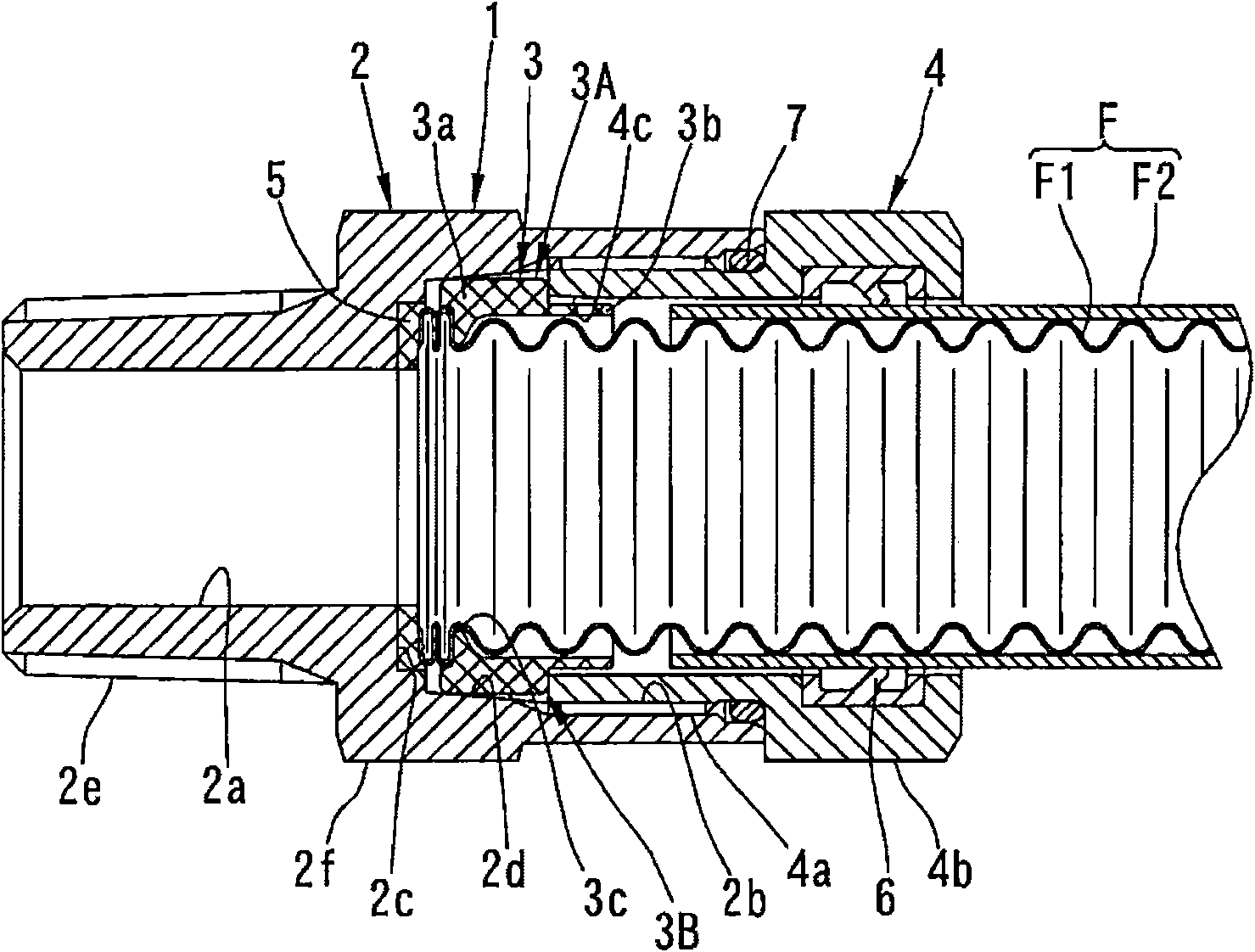
[0041] First, the flexible gas pipe F as the connecting object of the connecting device for flexible gas pipe according to the present invention will be described. Covering tube F2 constitutes. When the flexible gas pipe is connected to a gas machine, the front end of the cladding pipe F2 is cut off so that a predetermined number of peaks (for example, five peaks) are exposed from the front end of the bellows F1.

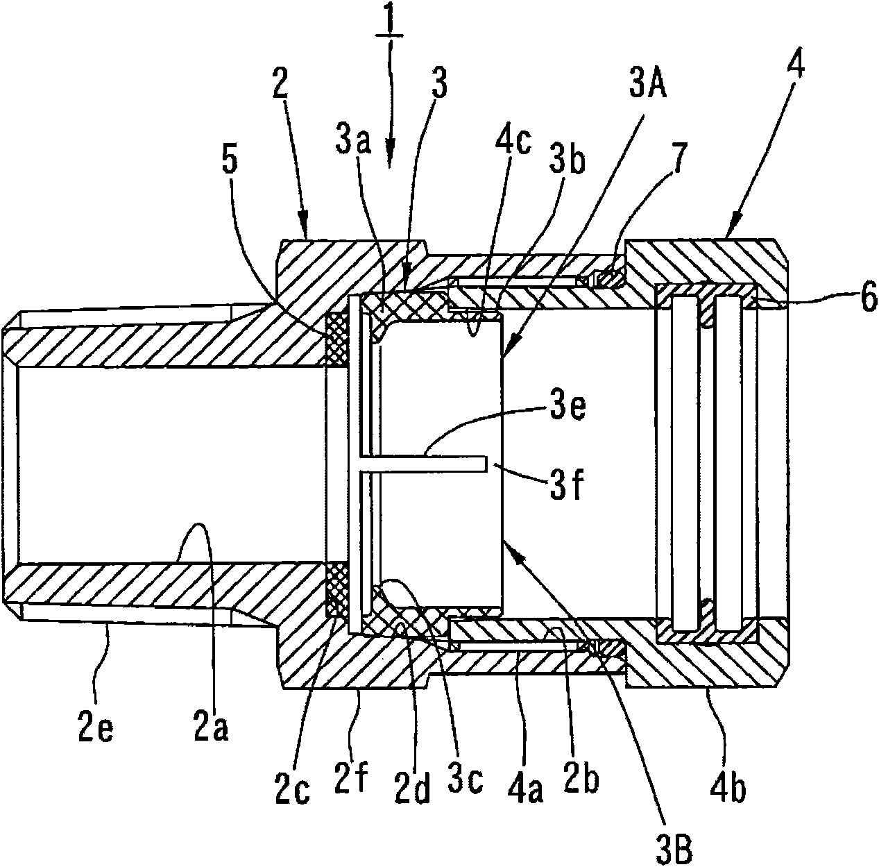
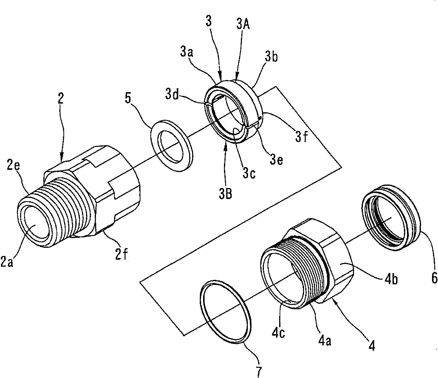
[0042] Next, a connecting device for a flexible gas pipe according to the present invention for connecting the above-mentioned flexible gas pipe F to gas equipment will be described. Figure 1 ~ Figure 3 A first embodiment of the present invention is shown. The flexible gas pipe connection device 1 of this embodiment has a device body 2 , a retainer 3 and a screw member 4 as main components.

[0043] A connection hole 2 a...


PUM


Abstract

The invention relates to a connecting device for a flexible gas tube. A corrugated tube provided with clamping parts can be easily inserted into a connecting hole even if a pair of clamping parts are separated. An inserting hole part (4c) is formed at the end part of the clamping parts (3A, 3B) side at the inner peripheral surface of a thread part (4) on the connecting hole (2a) of a device body (2) which is screwed with the thread part (4) and in the connecting device for the flexible gas tube which pushes and presses the pair of clamping piece parts (clamping parts) (3A, 3B) to move by the thread part (4). An annular protrusion part (3b) is formed at the end part of the thread part (4) side of the clamping piece parts (3A, 3B). The annular protrusion part (3b) is inserted into the inserting hole part (4c), thus maintaining the state that the clamping piece parts (3A, 3B) are positioned on the outer periphery of the corrugated tube (F1).

Description

technical field [0001] The present invention relates to a flexible gas pipe connecting device for connecting a flexible gas pipe to various gas equipment such as a gas pipe or a gas burner. Background technique [0002] A conventional connection device of this type has a device main body, a pair of engaging members, and a screw member, as described in Patent Document 1 below. A connection hole penetrating through the inside of the device body is formed. A bellows of a flexible gas tube is inserted into the connection hole through an opening at one end thereof. An annular abutting portion is formed on the inner peripheral surface of the connection hole toward the opening at one end thereof. The front end surface of the bellows inserted into the connection hole abuts against the abutting portion. A pair of engaging members are mounted immovably in the longitudinal direction on the outer peripheral portion located on the rear end side by only 2 to 3 peaks from the front end ...

Claims


Application Information

Patent Timeline
IPC IPC(8): F16L33/22
Inventor 宫川成一
Owner KOYO SANGYO CO LTD
Why Eureka
Try Eureka