
Eureka
For R&D, Eureka makes reading and utilizing patents & technical documents easy.
Eureka AIR
Designed for self-driven R&D workflows. Generate viable solutions, solve complex R&D challenges, empower your innovation with AI.

Eureka Materials
Designed for material experts only. Revolutionize your material R&D, from search, analyze, to developing new materials.

TechResearch
Generate reliable direction feasibility study reports for your R&D in just a few steps.

TechSeek
Discover and master advanced knowledge NOW. Basics, ideas, possibilities, all at once.

TechMind
As an expert in R&D Theories, TechMind can generates customized viable solutions instantly.

TechRisk
Analyze your overall solution with one click, know your potential R&D risks in advance.

TechMonitor
Get weekly tech updates, stay abreast of the latest tech innovations and key insights.
Method and device for charging fluoride salt bin on electrobath
A technology of feeding device and fluoride salt, applied in the field of electrolysis, can solve the problems of complex and high maintenance frequency, high investment cost and operating cost, cumbersome maintenance work, etc., and achieves easy construction operation and maintenance, simplified process and electrical control components. , the effect of reducing investment costs
- Summary
- Abstract
- Description
- Claims
- Application Information
AI Technical Summary
Problems solved by technology
Method used
Image

Examples
Embodiment 1
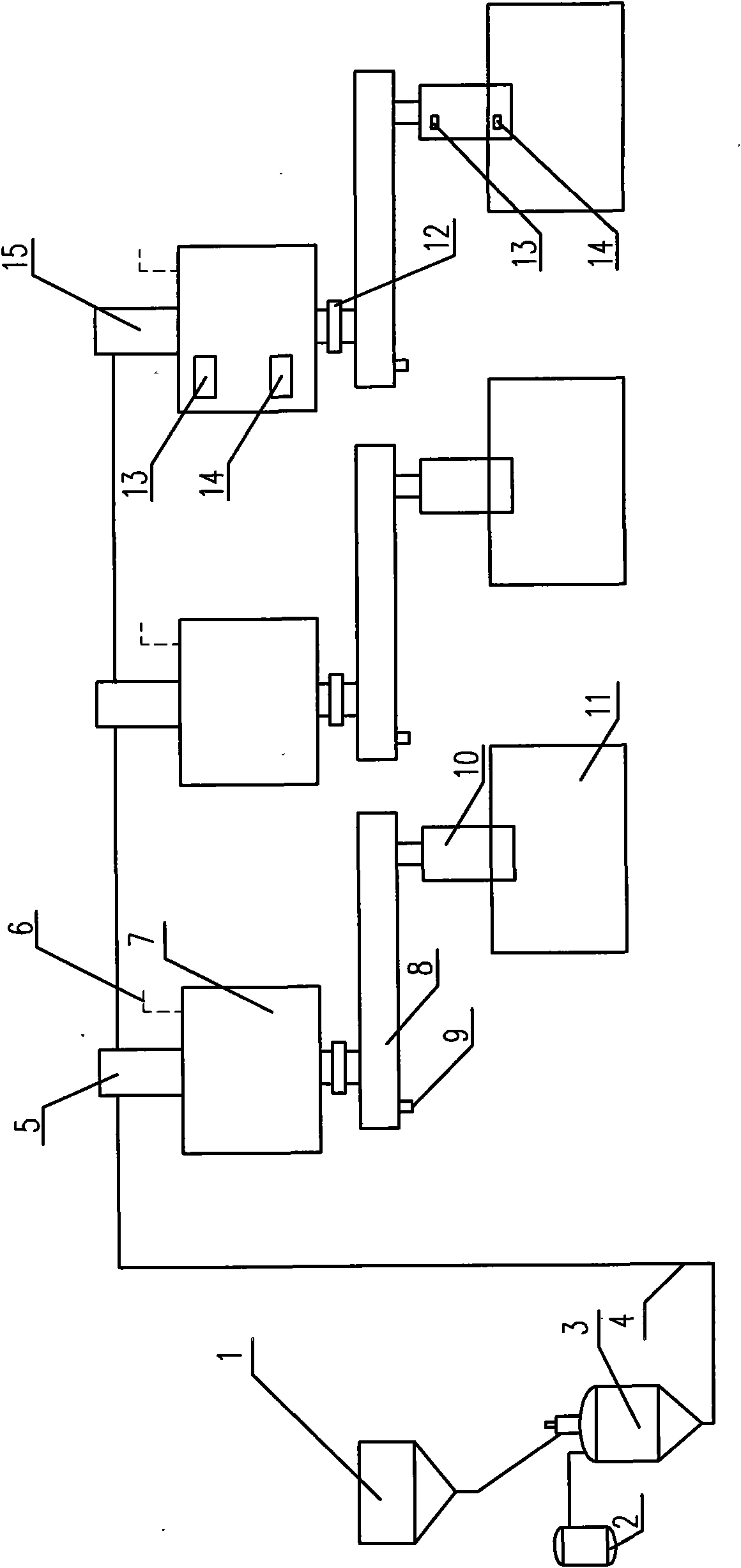
[0042] The feeding device of the fluoride salt tank on the electrolytic cell is as follows: figure 1 As shown, the connection mode of the dense phase conveying system is: the outlet of the fluoride salt silo 1 is connected to the inlet of the dense phase sending tank 3; the outlet of the dense phase sending tank 3 is connected to the dense phase conveying pipeline 4, and the dense phase conveying pipeline 4 is connected in series The material cutting device 5 is connected with a dense phase conveying bulking box 15 at the end, wherein the dense phase conveying pipeline 4 is connected with the unloading cutting device 5 and the dense phase conveying bulking box 15; the dense phase conveying bulking box 15 and each unloading The bottom of the material cutting device 5 is respectively connected to the top of an intermediate bin 7, and the intermediate bin 7 connected to the dense phase conveying expansion tank 15 is provided with a high material level switch 13 and a low material ...
Embodiment 2
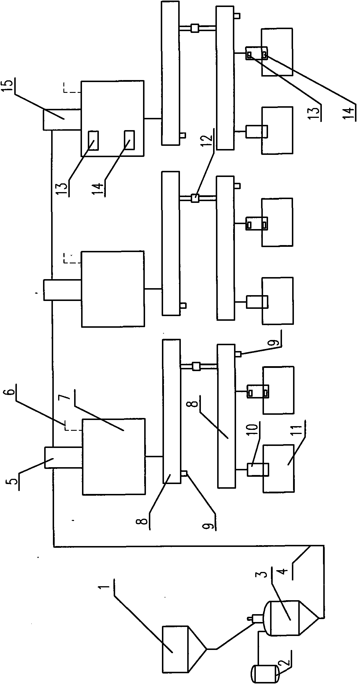
[0053] The feeding device of the fluoride salt tank on the electrolytic cell is as follows: figure 2 As shown, the connection mode of the dense phase conveying system is the same as that of Example 1; the difference is that the air outlet of the air exhaust device of the intermediate warehouse is connected with the upper chamber of the chute, and the air is exhausted through the air exhaust duct of the chute.
[0054] The source of air supply for the chute is the ultra-dense phase air supply system of the electrolysis workshop.
[0055] The connection between the intermediate warehouse and the chute system is as follows: the bottom of each intermediate warehouse is connected to a main chute, the outlet of the main chute is connected to a sub-chute, an insulating joint is provided between the sub-chute and the main chute, and the outlet of the sub-chute is connected to two fluorinated Salt bin. Below the fluoride salt hopper is an electrolytic cell. At least one of the fluor...
Embodiment 3
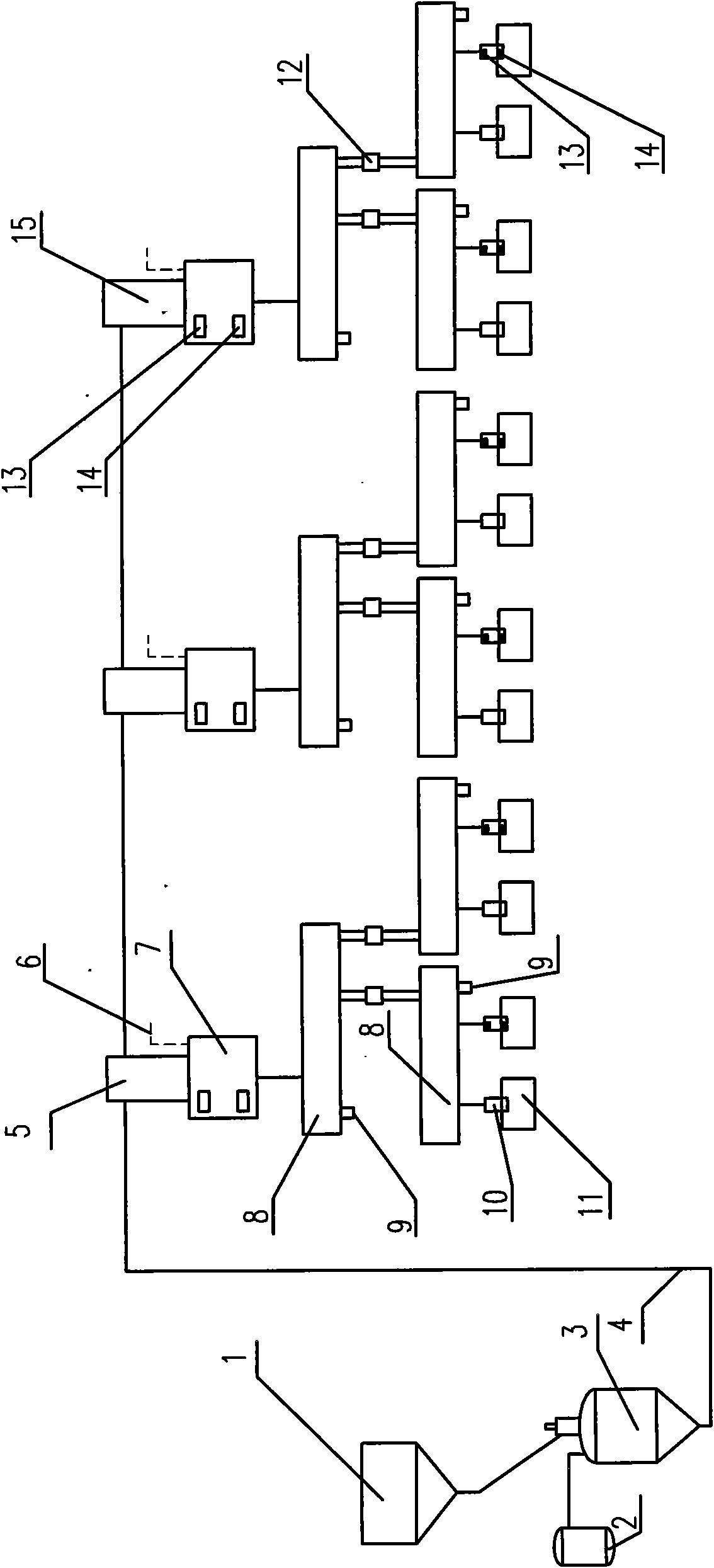
[0060] The feeding device of the fluoride salt tank on the electrolytic cell is as follows: image 3 As shown, the connection mode of the dense-phase conveying system is: the outlet of the fluoride salt silo is connected to the inlet of the dense-phase sending tank; the outlet of the dense-phase sending tank is connected to the dense-phase conveying pipeline, and the end of the dense-phase conveying pipeline is connected to a dense-phase conveying expansion tank , the dense-phase conveying pipeline connects two intermediate warehouses through a branch pipeline, and a hard-sealed pneumatic ball valve is installed on the branch pipeline, and the dense-phase conveying pipeline connects an intermediate warehouse through a dense-phase conveying expansion box; and the distance between two adjacent intermediate warehouses A hard-sealed pneumatic ball valve is installed on the main pipeline of the dense phase conveying pipeline, and a material level switch is installed on each intermed...
PUM
 Abstract
Description
Claims
Application Information
 - R&D Engineer
- R&D Manager
- IP Professional
- Industry Leading Data Capabilities
- Powerful AI technology
- Patent DNA Extraction
Browse by: Latest US Patents, China's latest patents, Technical Efficacy Thesaurus, Application Domain, Technology Topic, Popular Technical Reports.
© 2024 PatSnap. All rights reserved.Legal|Privacy policy|Modern Slavery Act Transparency Statement|Sitemap|About US| Contact US: help@patsnap.com