Movable automatic copying rail grinding machine

A profiling grinding, mobile technology, applied in the direction of track, track laying, track maintenance, etc., can solve the problems of high rail grinding accuracy, unsatisfactory, difficult grinding process control and adjustment, etc., to improve grinding accuracy, Simple structure, easy to move effect

Inactive Publication Date: 2009-10-28
常州霞穆轨道科技有限公司
View PDF0 Cites 21 Cited by
  • Summary
  • Abstract
  • Description
  • Claims
  • Application Information

AI Technical Summary

Problems solved by technology

[0002] With the large-scale speed-up of railways, the precision of railway rails, especially the straightness requirements, are getting higher and higher. On high-speed railways with a speed of 200 to 300 kilometers per hour, seamless steel rails are laid. It is a certain length The rails are connected by welding, and then the top and side surfaces of the welded rails are ground by grinding equipment until they meet the precision requirements. The current requirement for the straightness of the rails is: ≤±0.2mm, but as the train As the speed increases, the requirements for the straightness of the rail will be more stringent. Although the existing various forms of rail grinding machines are equipped with various forms of deflection in order to achieve the shape of the rail head when grinding the rail The way to meet the requirements, but when grinding the welded part of the rail, the rail grinding machine is independent of the rail to be polished and is separated from the rail, and is placed on the rail alone to grind the rail, so the grinding The rail machine and the rail lack a common benchmark, so it is difficult to precisely control and adjust the grinding process, and cannot meet the increasingly high precision of rail grinding, especially the flatness requirements

Method used


Image

  • Movable automatic copying rail grinding machine
  • Movable automatic copying rail grinding machine
  • Movable automatic copying rail grinding machine

Examples


Embodiment Construction

[0021] The present invention will be further described now in conjunction with accompanying drawing. These drawings are all simplified schematic diagrams, and only schematically show the configurations related to the present invention.

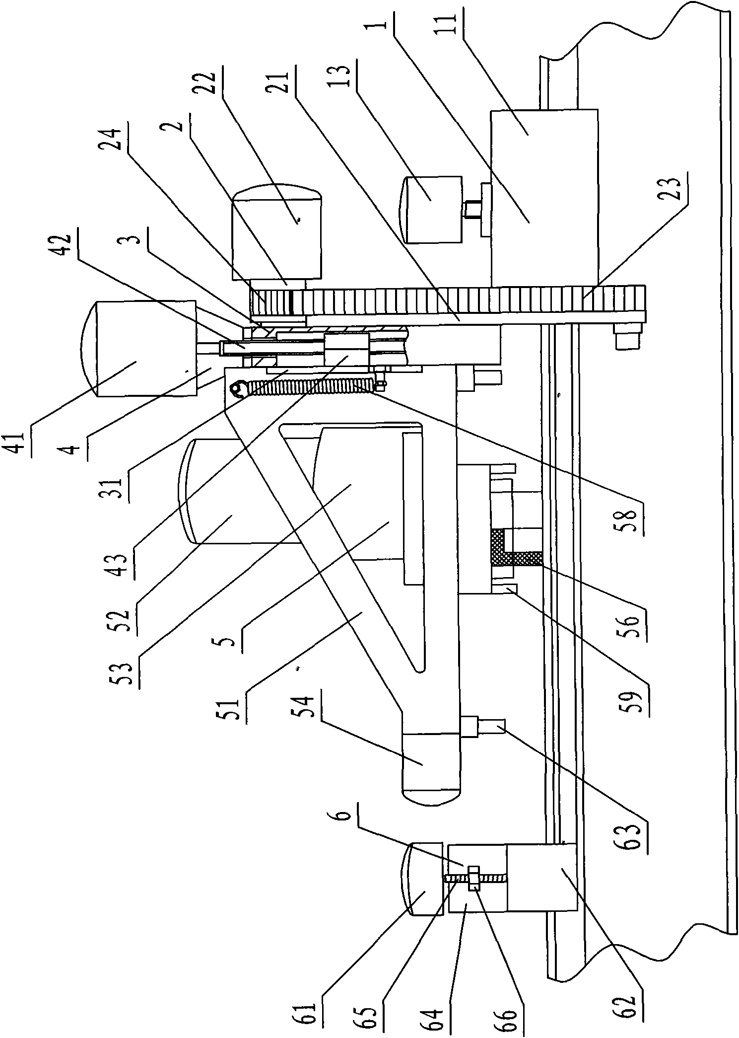
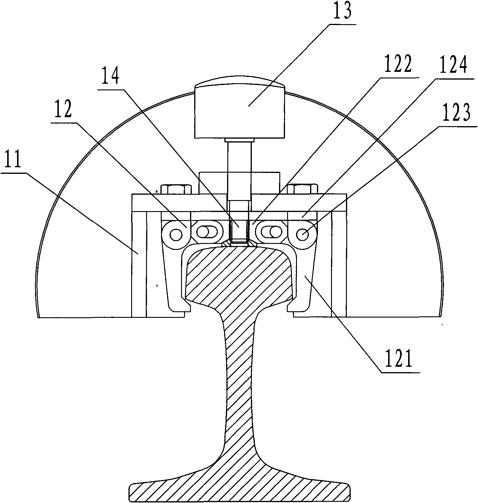
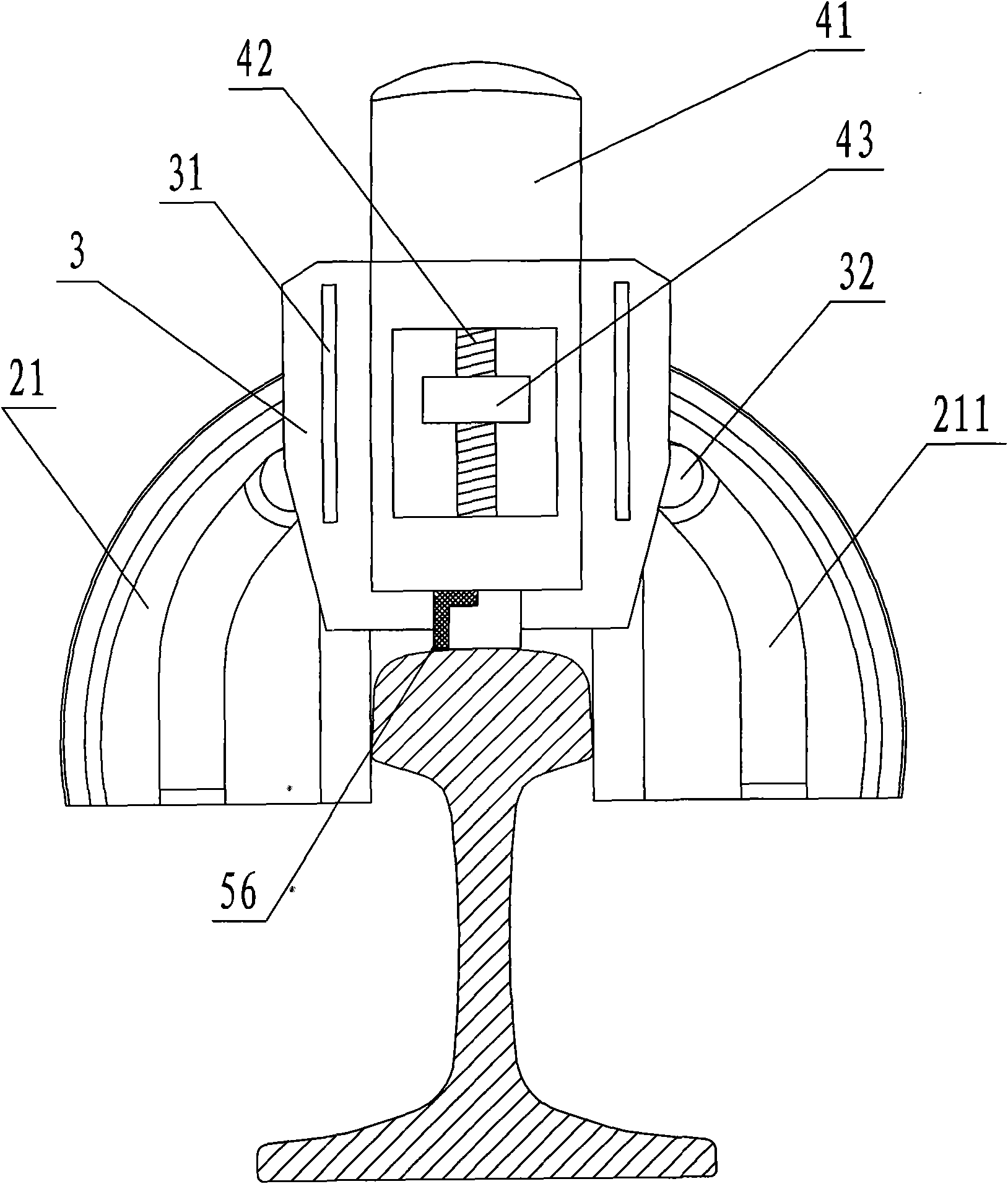
[0022] Such as Figure 1 to Figure 5 A mobile automatic profiling rail grinding machine shown includes a clamping device 1, a profiling device 2, a slider 3, a lifting device 4, a grinding device 5 and an adjusting device 6, and the clamping device 1 controls the rail grinding machine The whole is clamped and fixed on the top of the rail, the profiling device 2 is fixed on the clamping device 1, the grinding device 5 is slidably set on the slider 3 through the linear guide rail 31 provided on the slider 3, and the lifting device 4 is fixed on the The slider 3 can drive the grinding device 5 to move up and down along the surface of the slider 3. The slider 3 is fixed with the profiling device 2, and the profiling device 2 drives the grinding d...


PUM


Abstract

The invention discloses a movable automatic copying rail grinding machine, which comprises a clamping device, a copying device, a slider, a lifting device and a grinding device, wherein the clamping device can be clamped and fixed on the top of a rail; the copying device is fixed on the clamping device; the grinding device is slidably arranged on the slider through a rectilinear guide rail which is arranged on the slider; the lifting device is fixed on the slider and can drive the grinding device to lift up and down along the slider surface; the slider is fixed with the copying device which drives the grinding device to perform copying rotary motion with the same shape and track as the radial cross-section on the top of the rail through the slider; and the grinding device performs grinding processing on the top face and both side faces of the rail in turn along the rectilinear direction of the rail. The movable automatic copying rail grinding machine has a simple structure, is convenient to move, takes the rail as the unified reference under the condition of grinding, can perform high-precision grinding processing on the top face and the side faces of a welded position of the rail, and precisely controls and adjusts the grinding process so as to meet the higher and higher precision requirement of railway speed-raising on the rail.

Description

technical field [0001] The invention relates to a railway line maintenance machine, in particular to a mobile automatic profiling rail grinding machine suitable for grinding the top surface and side surfaces of the welded joints of rails on site. Background technique [0002] With the large-scale speed-up of railways, the requirements for the accuracy of railway rails, especially the straightness, are getting higher and higher. On high-speed railways with a speed of 200 to 300 kilometers per hour, seamless steel rails are laid. It is a certain length The rails are connected by welding, and then the top and side surfaces of the welded rails are ground by grinding equipment until they meet the precision requirements. The current requirement for the straightness of the rails is: ≤±0.2mm, but as the train As the speed increases, the requirements for the straightness of the rail will be more stringent. Although the existing various forms of rail grinding machines are equipped wit...

Claims


Application Information

Patent Timeline
IPC IPC(8): E01B31/17
Inventor 季关钰王德勤
Owner 常州霞穆轨道科技有限公司
Why Eureka
Try Eureka