Reflection grating

A reflective grating and reflective plate technology, applied in the field of optical imaging, can solve the problems of low transmittance of incident light of cylindrical grating, poor resistance to external light interference, complex production process, etc. , the effect of cost reduction

Inactive Publication Date: 2011-08-31
谢生豪
View PDF0 Cites 0 Cited by
  • Summary
  • Abstract
  • Description
  • Claims
  • Application Information

AI Technical Summary

Problems solved by technology

[0003] The present invention overcomes the shortcomings of the cylindrical grating, solves the shortcomings of the cylindrical grating, such as low incident light transmittance, poor ability to resist external light interference, complicated production process, and high manufacturing cost. Aligned reflectors instead of screen-diffusing, non-refractive grating devices

Method used


Image

  • Reflection grating
  • Reflection grating
  • Reflection grating

Examples


Embodiment Construction

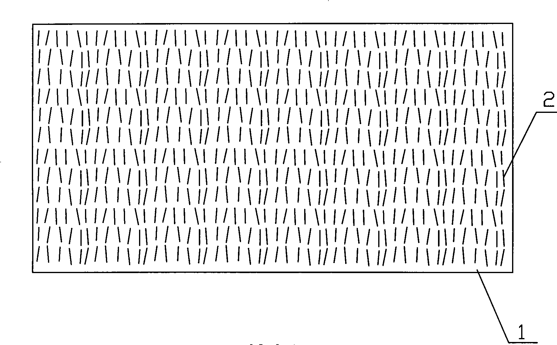
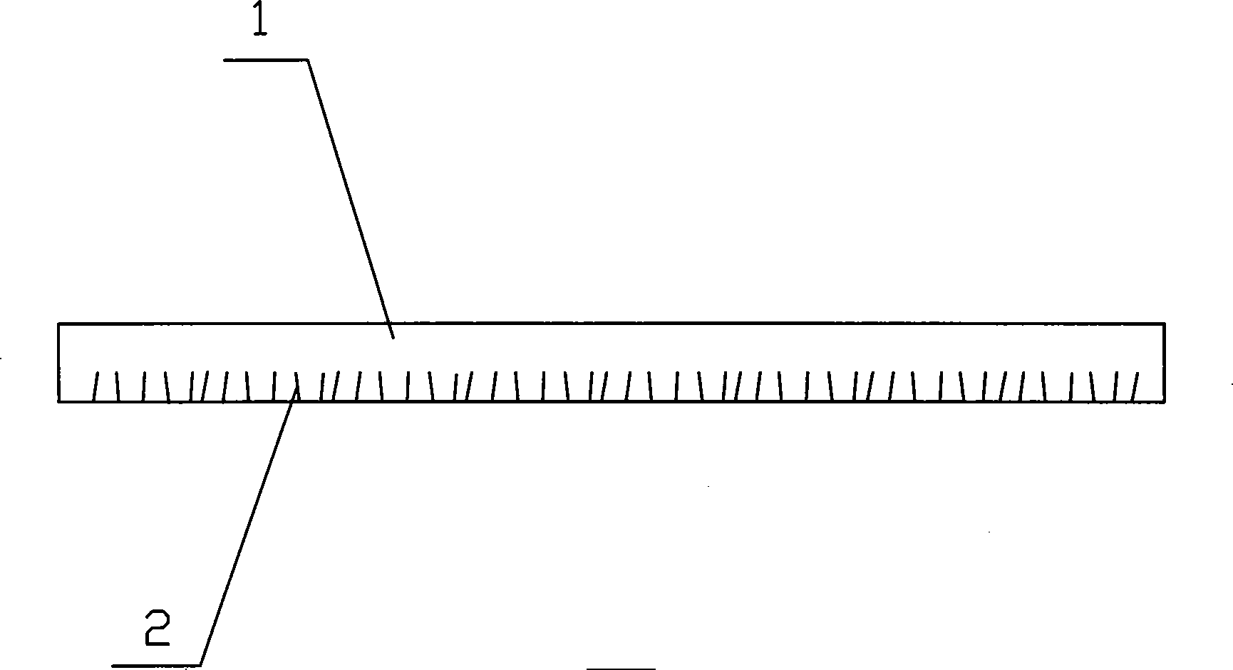
[0020] Such as Figure 1-3 As shown, a reflective grating is implanted with a black reflective plate 2 on a transparent plastic substrate 1 , and the reflective plate 2 is evenly distributed on the substrate 1 and forms an angle of 75° to 105° with the substrate 1 .

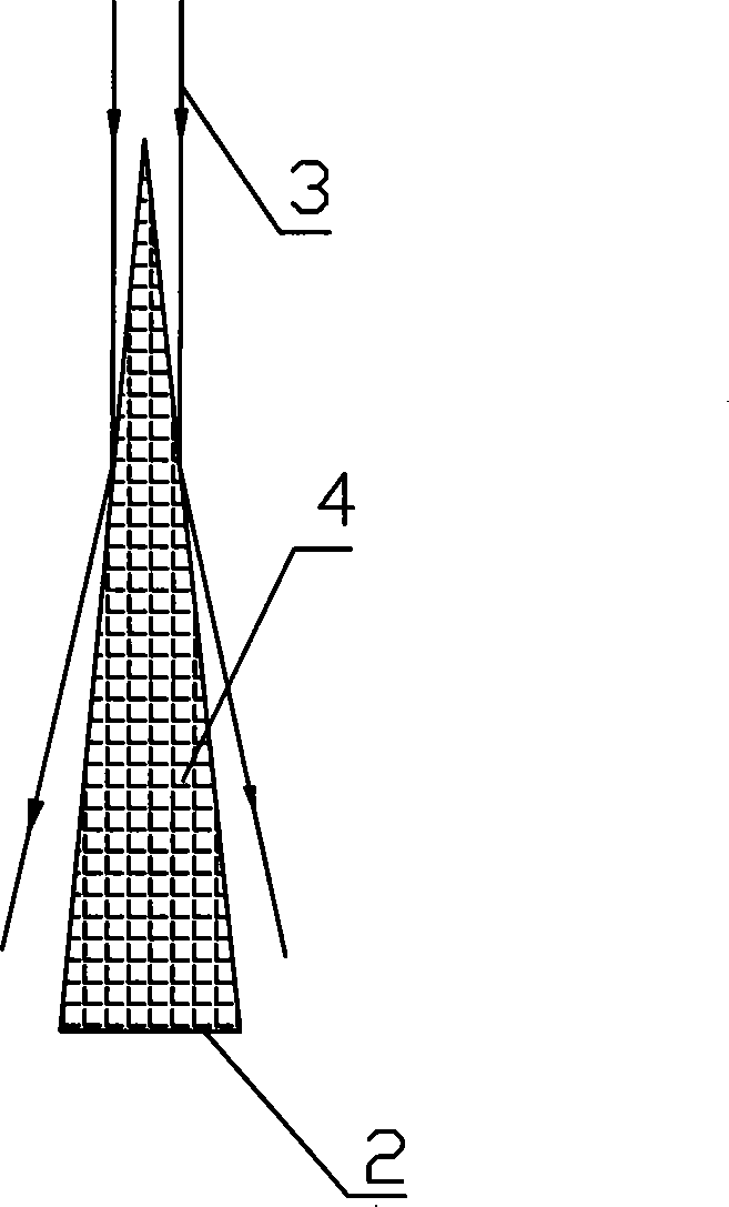
[0021] Substrate 1 is made of relatively optically dense material such as a polystyrene plate, with a refractive index n=1.59, and the reflector 2 is made of optically thin material, such as fluoroplastics, with a refractive index n=1.36 or other materials with a refractive index n less than 1.36. The plate 2 is filled with black carbon particles 4 and has a black appearance.

[0022] The thickness of the substrate 1 is 0.2-3mm, which is determined by the size of the substrate 1 and the requirements for mechanical rigidity. The thickness of the reflection plate 2 is less than 0.02mm, and the distance between the reflection plates 2 is 10 times of the thickness of the plate.

[0023] Such as Figure 4 As shown:...


PUM


Abstract

The invention relates to a reflection grating which comprises a base plate and a reflecting plate, wherein the reflecting plate is planted into the base plate, the base plate is made of transparent optical denser materials, and the reflecting plate is made of optically thinner materials. The invention overcomes the insufficiency of the traditional grating and develops the grating with high incident light transmission ratio, strong external light anti-interference ability, simple production process, low manufacturing cost, and the like.

Description

technical field [0001] The invention relates to the field of optical imaging, in particular to a grating device utilizing the principle of reflection. Background technique [0002] At present, the most widely used projection screen grating is cylindrical grating. The cylindrical grating first converts the incident light source into parallel light through the Fresnel lens, and then refracts the light through the cylindrical mirror on the grating, so that the light converges and passes through the cylinder. The black stripes in front of the mirror shot out from the gap. This kind of grating has the following disadvantages: because the transmitted light can only be emitted from the black strip gap in front of the cylindrical mirror, the light transmittance of the grating is low, but if the gap is increased, the contrast of the grating will be insufficient; the light is refracted many times, Dispersion is prone to occur; the cylindrical grating must be used with the Fresnel len...

Claims


Application Information

Patent Timeline
Patent Type & Authority Patents(China)
IPC IPC(8): G02B5/18
Inventor 谢生豪
Owner 谢生豪
Why Eureka
Try Eureka