
Switch type regulating circuit and double-coil motor device

A technology for adjusting circuits and double coils, applied in the field of circuits, can solve problems such as reducing the overall circuit operation efficiency and charge flow.

Active Publication Date: 2011-05-11
ADVANCED ANALOG TECH INC
View PDF4 Cites 0 Cited by
  • Summary
  • Abstract
  • Description
  • Claims
  • Application Information

AI Technical Summary

Problems solved by technology

[0006] In view of this, how to prevent the charge flow caused by the conduction of parasitic elements and reduce the operating performance of the overall circuit is an urgent problem to be solved in the industry.

Method used


Image

  • Switch type regulating circuit and double-coil motor device
  • Switch type regulating circuit and double-coil motor device
  • Switch type regulating circuit and double-coil motor device

Examples


Embodiment Construction

[0036] The content of the present invention will be explained through the following examples. However, the examples of the present invention are not intended to limit the present invention to be implemented in any specific environment, application or special method as described in the examples. Therefore, the descriptions about the embodiments are only for the purpose of explaining the present invention rather than limiting the present invention. It should be noted that in the following embodiments and drawings, elements not directly related to the present invention have been omitted and not shown.

[0037]A preferred embodiment of the present invention is shown in FIG. 5, which mainly shows a switchable adjustment circuit 40a, 40b of a double-coil motor device 4, each of which includes gate-controlled switching elements 41a, 41b and drive circuits 49a, 49b, wherein the switchable The adjustment circuits 40a and 40b are the same regardless of the connection, function and desir...


PUM


Abstract

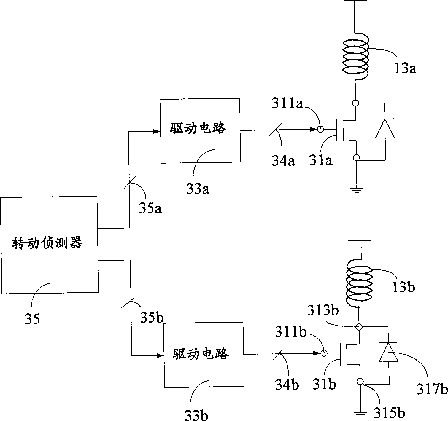
The invention relates to a switch type regulating circuit for a double-coil motor device, which comprises a grid-control switching element and a drive circuit. When an induction voltage signal generated by one coil in double coils exceeds a reference value, the drive circuit generates an output signal to conduct the grid-control switching element, and thereby the damage of an integral circuit by conducting a parasitic diode of the grid-control switching element can be prevented.

Description

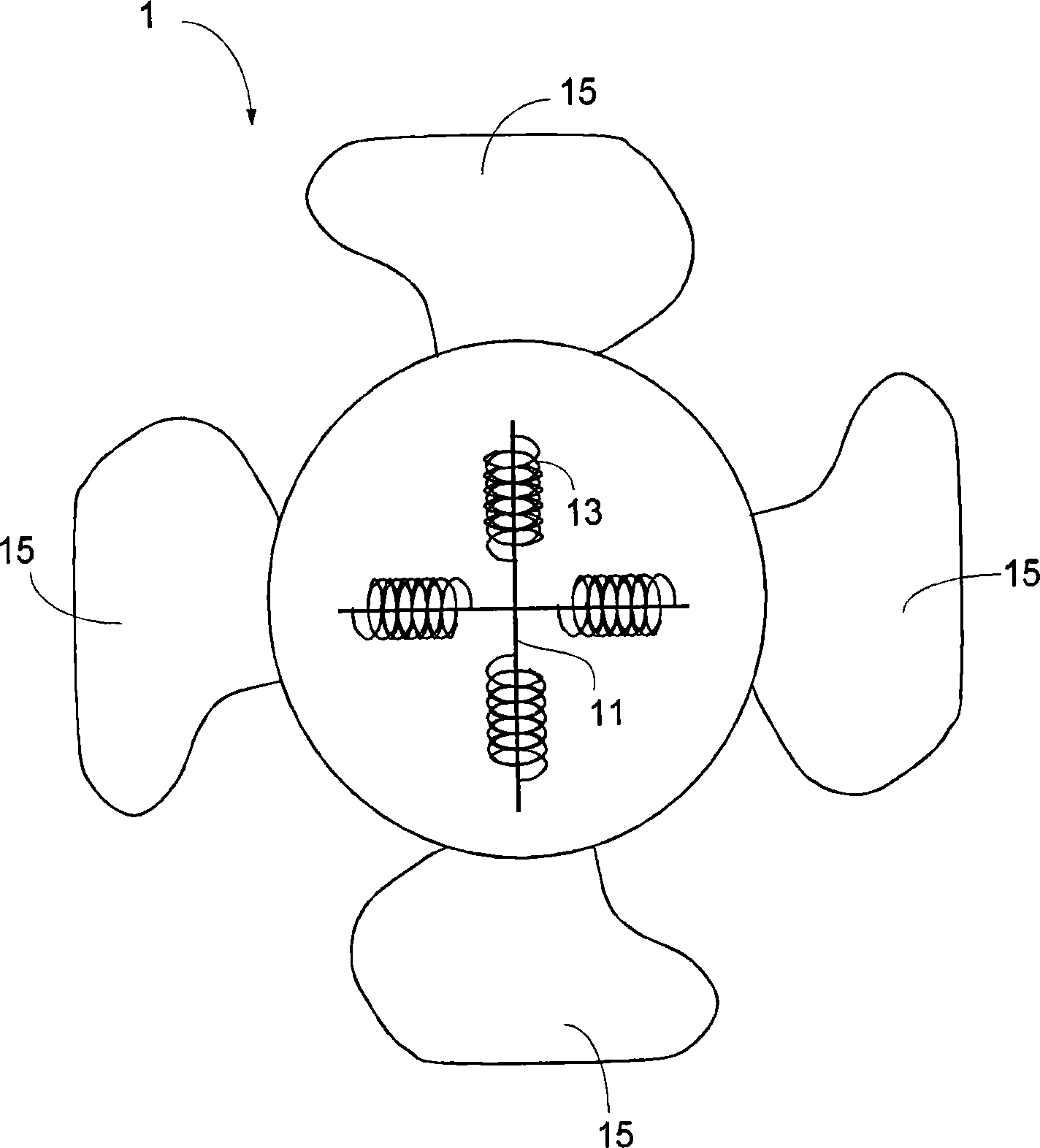
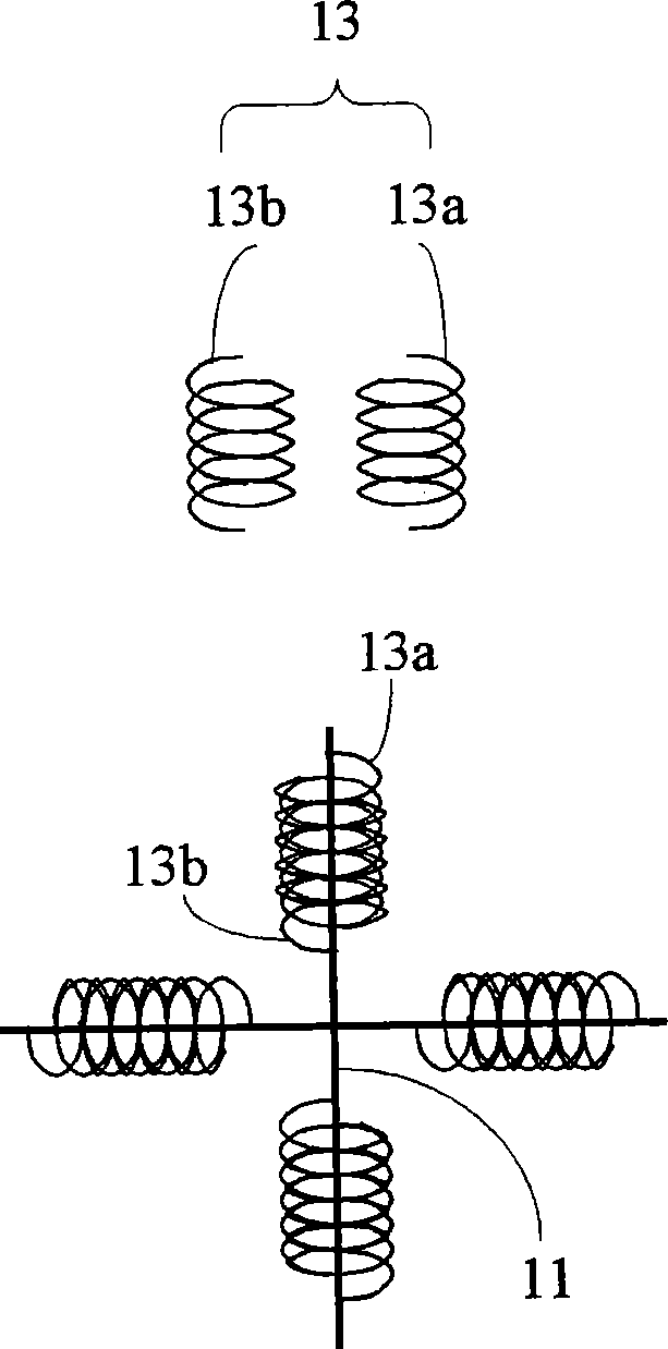
technical field [0001] The present invention relates to a circuit for a double-coil motor device, in particular to a switchable adjustment circuit which can prevent the circuit from malfunctioning. Background technique [0002] In many electronic products, a large amount of heat is generated due to the thermal effect of the current when the circuit is in operation. At this time, a fan motor is needed to assist the electronic product to dissipate heat when the circuit is in operation. One of the devices commonly used to control fan motors is the use of dual coil motor devices such as figure 1 As shown, it is a schematic diagram of a double-coil motor device 1, and its operation is to pass current to one of the double coils 13 wound on the stator 11 of the double-coil motor device 1, due to the connection between the coil and the rotor The magnetic force drives the fan 15 to rotate, and the winding method for the double coils 13 on the same stator 11 is: one of the coils 13a ...

Claims


Application Information

Patent Timeline
Patent Type & Authority Patents(China)
IPC IPC(8): H02P7/28
Inventor 陈炫全林登财
Owner ADVANCED ANALOG TECH INC
Learn More