

Three-phase motor rotor
A technology of three-phase motors and rotors, which is applied in the direction of electrical components, electromechanical devices, electric components, etc., can solve the problems of sparks and inability to use, and achieve the effect of preventing excessive temperature and reducing waste
- Summary
- Abstract
- Description
- Claims
- Application Information
AI Technical Summary
Problems solved by technology
Method used
Image

Examples
Embodiment Construction
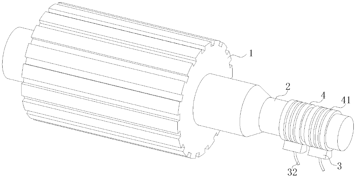
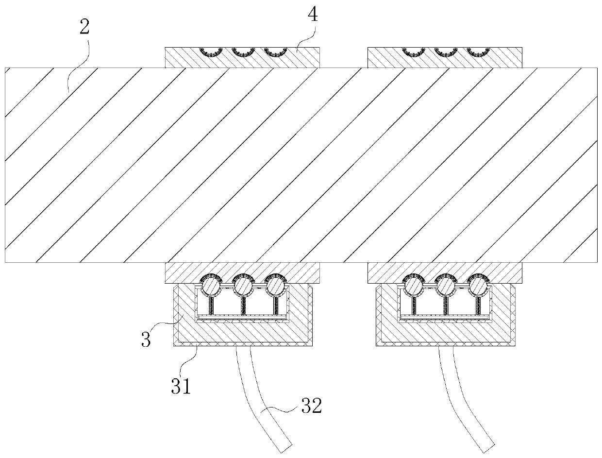
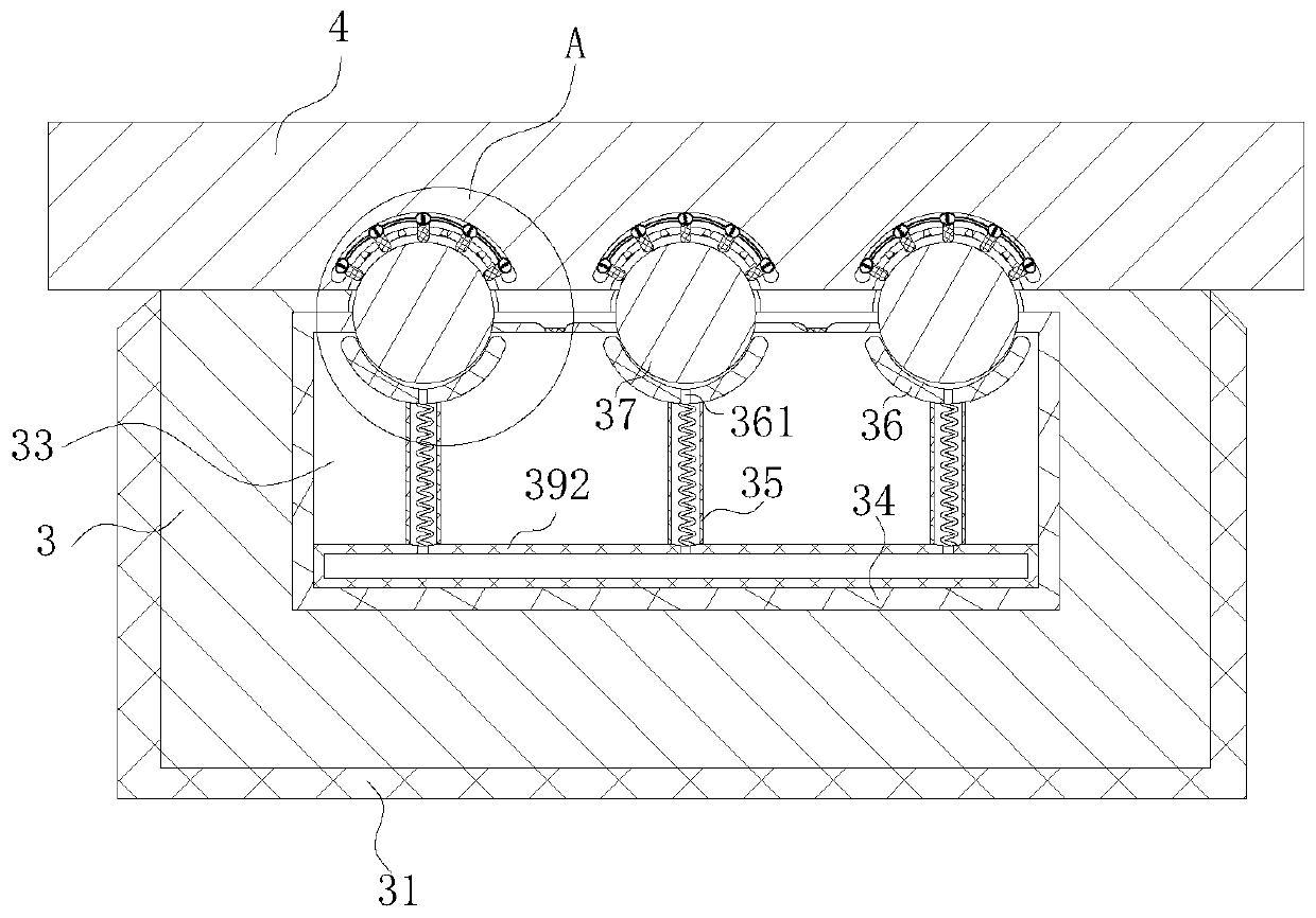
[0021] use Figure 1-Figure 5 A rotor of a three-phase motor according to an embodiment of the present invention is described as follows.
[0022] like Figure 1-Figure 5As shown, a three-phase motor rotor according to the present invention includes a rotor 1, a drive shaft 2, a brush 3 and a slip ring 4; the inner wall of the rotor 1 is fixedly connected with the drive shaft 2 at the centerline position, and The drive shaft 2 is designed to protrude from the rotor 1; the outer surface of the drive shaft 2 is fixedly connected with evenly arranged collector rings 4, and the number of collector rings 4 is two; the outer surfaces of the two collector rings 4 are all slidingly connected There are brushes 3; the outer surfaces of the two brushes 3 are wrapped with an insulating layer 31; the inner walls of the two brushes 3 are fixed with wires 32, and the wires 32 are connected to the power supply through the insulating layer 31; Long grooves 33 are provided in the inner walls ...
PUM
 Abstract
Description
Claims
Application Information