Multi-track magnetic motor and control method thereof

A magnetic motor and permanent magnet technology, applied in the direction of electrical components, electromechanical devices, electric components, etc., can solve the problems that permanent magnets cannot be fully utilized, and the energy of permanent magnet motors cannot be fully converted, so as to avoid the phenomenon of cutting magnetic induction lines, Avoid magnetic flux leakage and high efficiency

Inactive Publication Date: 2018-02-23
蔡晓青
View PDF0 Cites 3 Cited by
  • Summary
  • Abstract
  • Description
  • Claims
  • Application Information

AI Technical Summary

Problems solved by technology

The permanent magnet motor is a kind of motor that uses permanent magnets to generate an excitation magnetic field. After the permanent magnet motor is supported, it does not need external energy to maintain its magnetic field. The existing permanent magnet motor cannot make full use of the permanent magnet due to the setting of the permanent magnet. magnetic field, the energy of the existing permanent magnet motor cannot be fully converted, so the existing permanent magnet motor can only be used in low-power occasions

Method used


Image

  • Multi-track magnetic motor and control method thereof
  • Multi-track magnetic motor and control method thereof
  • Multi-track magnetic motor and control method thereof

Examples


Embodiment 1

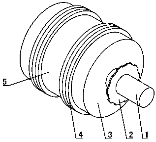
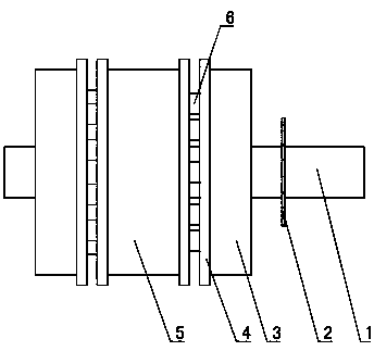
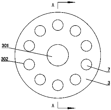
[0044] Such as Figure 1~2As shown: in this embodiment, two stators 4 are provided, and a rotor is arranged symmetrically on both sides of each stator 4, and the permanent magnets 7 on adjacent rotors on both sides of each stator 4 correspond one-to-one, and the two The two opposite permanent magnets 7 on the rotor are coaxially arranged, the polarities of the two opposite permanent magnets 7 on the two rotors are oppositely arranged, and the two rotors arranged between the two stators 4 are integrally arranged, thereby simplifying the motor assembly process. The two stators 4 are coaxially installed in the casing of the motor, the rotor is coaxially installed on the main shaft 1, the main shaft 1 is installed in the casing through the bearing rotation, and the main shaft 1 is coaxially arranged with the casing, and one end of the main shaft 1 Extend out of the casing to form the output shaft of the motor. The phase detection module is arranged between the casing and the mai...

Embodiment 2

[0070] Such as Figure 9 Shown: the difference between embodiment 2 and embodiment 1 is that the cross section of the permanent magnet 7 is fan-shaped. And in this embodiment, there are three stators 4 .

Embodiment 3

[0072] The difference between embodiment 3 and embodiment 1 is that a second mounting plate 5 is arranged between the two stators 4, permanent magnets 7 are embedded in both ends of the second mounting plate 5, and the outer sides of each stator 4 are the same. The shaft is provided with an iron plate, and the diameter of the iron plate is equal to the diameter of the second mounting plate 5 .


PUM


Abstract

A multi-track magnetic motor and a control method thereof belong to the technical field of motors. It is characterized in that: the side of the rotor close to the stator (4) is provided with a plurality of installation holes, the permanent magnets (7) are embedded in the installation holes of the installation plate, and even number of permanent magnets (7) are arranged in a ring and evenly spaced, phase The polarities of the adjacent permanent magnets (7) are oppositely set; the stator (4) is provided with a plurality of coils arranged in a ring and evenly spaced, the number of coils on the stator (4) and the permanent magnet on the rotor matched with it (7) are equal in number. This multi-track magneto makes full use of the exciting magnetic field of the permanent magnet. The rotor is made of magnetically conductive material, which avoids the occurrence of magnetic flux leakage and improves the energy conversion rate of the motor. The efficiency of the motor is high. The rotor rotates synchronously with the permanent magnet. The occurrence of the phenomenon of cutting the magnetic induction line is avoided; the excitation magnetic field of the permanent magnet fully utilized by the control method of the multi-track magneto motor has no dead angle, and the motor can be started by using a small current.

Description

technical field [0001] A multi-track magnetic motor and a control method thereof belong to the technical field of motors. Background technique [0002] Motor refers to an electromagnetic device that converts or transmits electric energy according to the law of electromagnetic induction. Its main function is to generate driving torque as a power source for electrical appliances or various machines. The permanent magnet motor is a kind of motor that uses permanent magnets to generate an excitation magnetic field. After the permanent magnet motor is supported, it does not need external energy to maintain its magnetic field. The existing permanent magnet motor cannot make full use of the permanent magnet due to the setting of the permanent magnet. Therefore, the existing permanent magnet motor can only be used in low-power occasions. Contents of the invention [0003] The technical problem to be solved by the present invention is to overcome the deficiencies of the prior art ...

Claims


Application Information

Patent Timeline
Patent Type & Authority Applications(China)
IPC IPC(8): H02K16/00H02K11/22
CPCH02K16/00H02K11/22
Inventor 蔡晓青
Owner 蔡晓青
Why Eureka
Try Eureka