
Internal combustion steam boosting take-off unit of airplane

An aircraft and booster technology, applied in aircraft parts, auxiliary power equipment, transportation and packaging, etc., can solve the problems of huge mass, insufficient power, low efficiency, etc., to achieve high output power, increased fuel capacity, high pressure effect

Inactive Publication Date: 2012-10-24
李文铎
View PDF8 Cites 14 Cited by
  • Summary
  • Abstract
  • Description
  • Claims
  • Application Information

AI Technical Summary

Problems solved by technology

[0014] The purpose of the present invention is to propose an internal combustion steam type aircraft booster to solve the problems of insufficient power, low efficiency, huge mass and complex structure of the existing aircraft booster in the prior art.

Method used


Image

  • Internal combustion steam boosting take-off unit of airplane
  • Internal combustion steam boosting take-off unit of airplane
  • Internal combustion steam boosting take-off unit of airplane

Examples


Embodiment

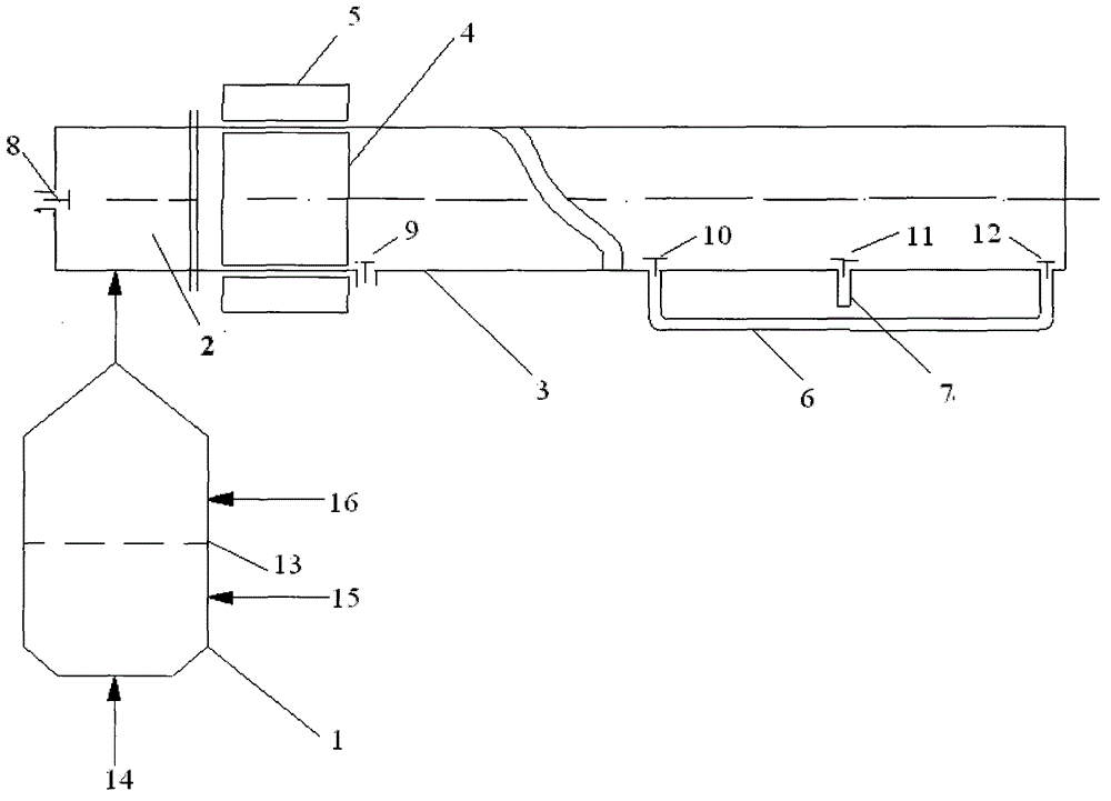
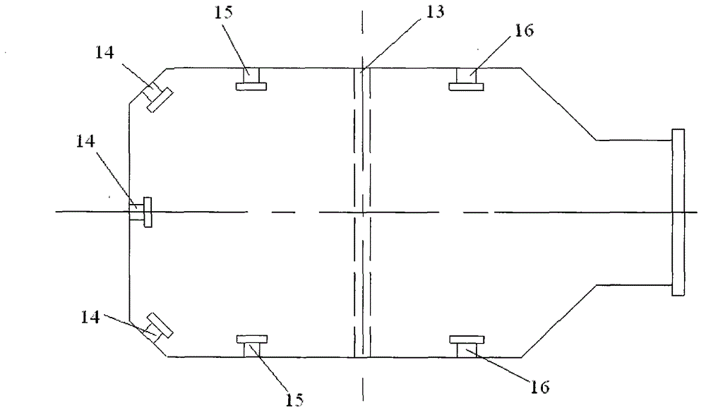
[0042] As a device for catapult take-off of aircraft carrier aircraft, internal combustion steam aircraft booster launcher, such as figure 1 As shown, it includes a combustion chamber 1, a balance chamber 2, a cylinder 3, an electromagnetic piston 4, an electromagnetic collar 5, a vent pipe 6 and a vent pipe 7; the outlet of the combustion chamber 1 is connected to the balance chamber 2 through a pipeline; the electromagnetic piston 4 is in The inside of the cylinder 3 can slide and move; the electromagnetic collar 5 is set on the outside of the cylinder 3; the electromagnetic collar 5 follows the electromagnetic force of the electromagnetic piston 4; there are 4 valves on the side wall of the cylinder 3; Combustion chamber 1 is a cylinder, such as figure 2 As shown, there is a catalyst net 13 in the middle, and there are oil injection holes 14 and air injection holes 15 at the bottom, and high-pressure fuel (enters the combustion chamber 1 through the oil injection holes 14)...


PUM


Abstract

The invention relates to an internal combustion steam boosting take-off unit of an airplane, and belongs to the technical field of boosting take-off technology of airplanes. The internal combustion steam boosting take-off unit of the airplane comprises a combustion chamber, a balancing chamber, an air cylinder, an electromagnetic piston, an electromagnetic lantern ring, a breather pipe, a blow-off pipe and five valves. The outlet of the combustion chamber is connected with the balancing chamber through a pipeline. The electromagnetic piston is arranged inside the air cylinder and can slide and move. The electromagnetic lantern ring is sleeved outside the air cylinder. The electromagnetic lantern ring follows up under the effect of an electromagnetic force of the electromagnetic piston. A valve is arranged at the left end of the balancing chamber. Four of five valves are arranged on the side wall of the air cylinder. The combustion chamber is provided with a catalyst net, an oil spray hole, a gas injection hole and a water injection hole. High-pressure oil and high-pressure oxygen combust in the combustion chamber to generate gas. High-pressure water enters the combustion chamber through the water injection hole and steam turns into vapor. Then the vapor and the gas enter the balancing chamber to push the electromagnetic piston to move and the electromagnetic lantern ring follows up. The internal combustion steam boosting take-off unit of the airplane provided by the invention is small in electromagnetic energy consumption and light and simple in device. The internal combustion steam boosting take-off unit of the airplane provided by the invention is high in energy conversion ratio, energy-saving, economic and environment-friendly.

Description

technical field [0001] The invention relates to an internal-combustion steam type aircraft booster takeoff, and belongs to the technical field of aircraft booster takeoff. Background technique [0002] One of the key technologies of an aircraft carrier is the carrier-based aircraft catapult take-off system. Aircraft catapult-assisted take-off has a long history. When the Wright brothers invented the aircraft, Langley invented the method of assisted take-off with springs and slides. Since then, there have been falling weight, flywheel, rocket, hydraulic, pneumatic and so on. In 1922, the first US aircraft carrier was named USS Langley. Both the Triumph and Courage aircraft carriers of the United Kingdom use compressed air as power (air pressure method), and use pulleys and steel cables to transmit energy to eject aircraft, and the maximum work reaches 5000kJ (5MJ). In 1943, the USS Enterprise used a hydraulic catapult, model H2-1, which could accelerate a 5.5 ton aircraft ...

Claims


Application Information

Patent Timeline
Patent Type & Authority Applications(China)
IPC IPC(8): B64D41/00
Inventor 李文铎尹建锋李宬
Owner 李文铎
Learn More