Network surveillance system

A technology for sensing areas and sensing data, applied in the field of monitoring systems, which can solve problems such as inability to find common image features, reliance on a large number of overlaps and complete connectivity, and uncharacterized active topology

Active Publication Date: 2009-10-28
SNAP NETWORK SURVEILLANCE PTY
View PDF0 Cites 2 Cited by
  • Summary
  • Abstract
  • Description
  • Claims
  • Application Information

AI Technical Summary

Problems solved by technology

These methods do not characterize active topology, are susceptible to inability to find the required number of common image features, and rely on substantial overlap and full connectivity between fields of view

Method used


Image

  • Network surveillance system
  • Network surveillance system
  • Network surveillance system

Examples


Embodiment Construction

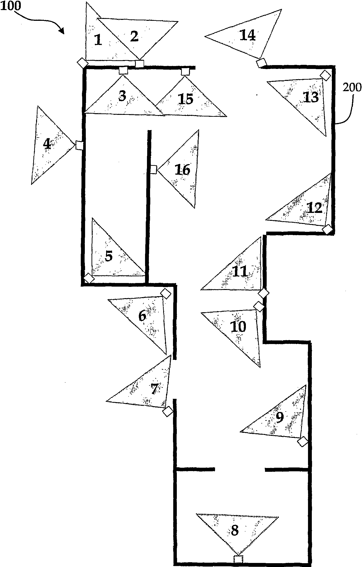
[0047] now refer to figure 1, which shows a schematic diagram of a network monitoring system 100 distributed around a building 200 for monitoring a wide area inside and outside the building. In this exemplary embodiment, the network monitoring system 100 includes a camera network comprising sixteen (16) individual IP cameras 1, 2...16 that transmit their images in real time to a centralized monitoring site. Each camera has a corresponding field of view, which is shown symbolically as a shaded area extending from the camera position.

[0048] Although the network monitoring system 100 shown here includes cameras having substantially similar features, it will be apparent that the invention is equally applicable to cameras or sensor networks that include cameras with a wide range of resolutions and other imaging characteristics. Many different types of cameras or sensors. like figure 1 As shown in , many fields of view of separate cameras will overlap due to their positioning...


PUM


Abstract

A method for estimating the activity topology of a set of sensed data windows is described. Each of the sensed data windows related to a corresponding sensed region. The method includes the steps of determining a subset of sensed data windows that are not connected through comparing sensed data windows pair wise from the set of sensed data windows, wherein the step of comparing sensed data windows pair wise includes determining whether a pair of sensed data windows does not have overlapping sensed regions: determining a first occupancy measure for a first sensed data window and a second occupancy measure for a second sensed data window, the first and second sensed data windows comprising the pair of sensed data windows, and comparing the first and second occupancy measures so as to determine that the associated first and second sensed data windows do not overlap; and excluding the subset of sensed data windows from the set of sensed data windows. In one embodiment, the sensed data windows corresponding to image windows such as would be provided by a visual surveillance system.

Description

[0001] priority statement [0002] This patent application claims priority to Australian Provisional Patent Application No. 2006906433, entitled "Network Surveillance System", filed 20 November 2006, the entire content of which is hereby expressly incorporated by reference. technical field [0003] The present invention relates to monitoring systems. In particular, the present invention relates to monitoring systems involving a network of multiple sensors distributed over a wide area. Background technique [0004] With the increased focus on monitoring private and public areas, the number and complexity of cameras and sensors used to monitor these vast areas has increased significantly. an example of such a monitoring task is the surveillance of an airport or train station, which may involve hundreds of cameras, each capable of providing live feeds to a centralized monitoring station where they are viewed by human operators . Operators can have several possible goals, suc...

Claims


Application Information

Patent Timeline
Patent Type & Authority Applications(China)
IPC IPC(8): H04N7/18
CPCG08B13/19656G08B13/19645H04N7/18G06V20/52G06V10/62
Inventor 安东·约翰·万登亨格尔安东尼·罗伯特·迪克迈克尔·约翰·布鲁克斯
Owner SNAP NETWORK SURVEILLANCE PTY
Why Eureka
Try Eureka