Orthopaedic foot component and method for controlling an artificial foot

A foot fitting and orthopedic technology, applied in the field of controlling such orthopedic foot fittings, can solve problems such as heavy weight and large battery volume.

Active Publication Date: 2009-11-04
OTTO BOCK HEALTHCARE IP GMBH & CO KG
View PDF7 Cites 26 Cited by
  • Summary
  • Abstract
  • Description
  • Claims
  • Application Information

AI Technical Summary

Problems solved by technology

For this purpose the prosthetic wearer has to carry a high performan

Method used


Image

  • Orthopaedic foot component and method for controlling an artificial foot
  • Orthopaedic foot component and method for controlling an artificial foot
  • Orthopaedic foot component and method for controlling an artificial foot

Examples


Embodiment Construction

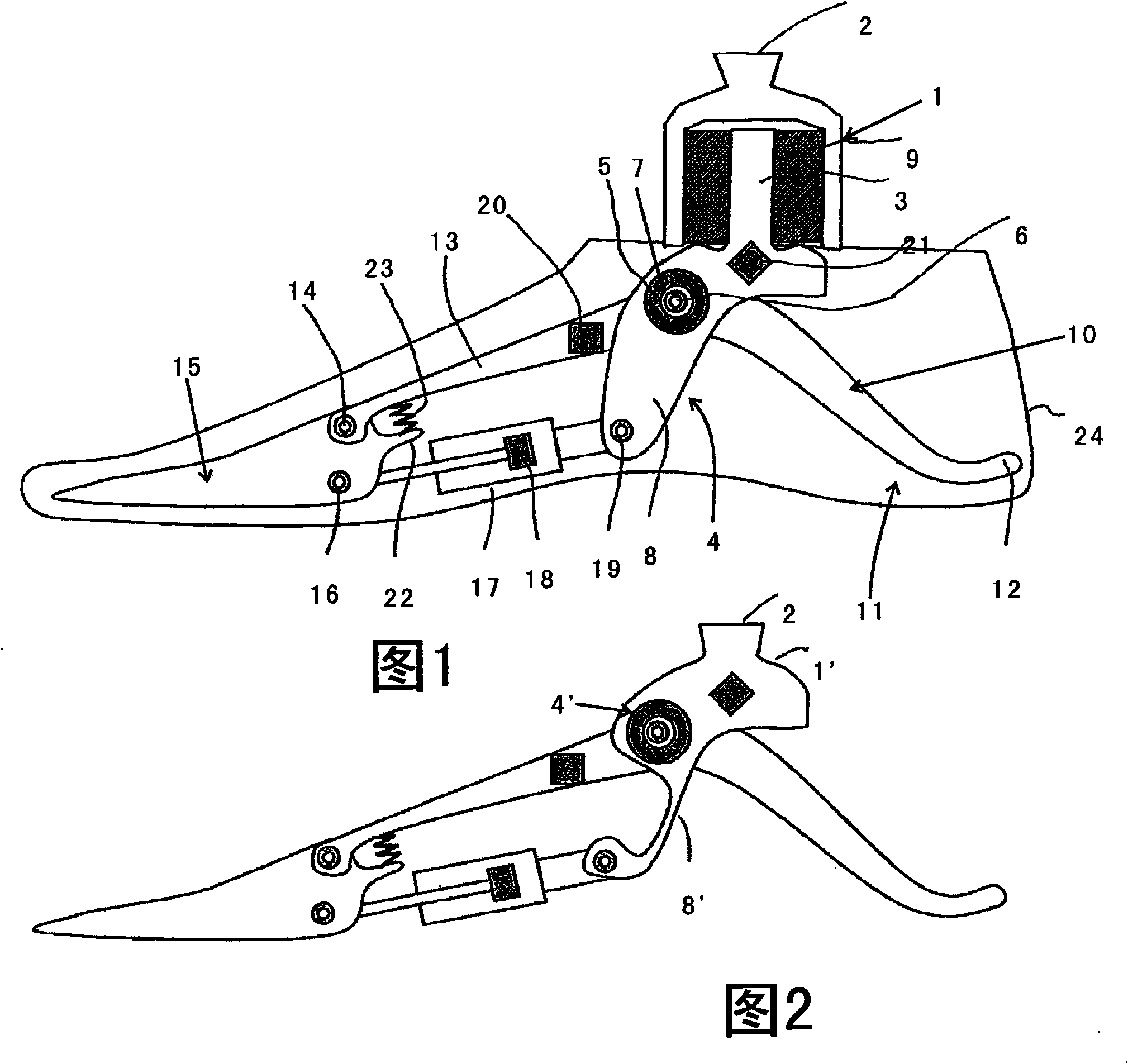
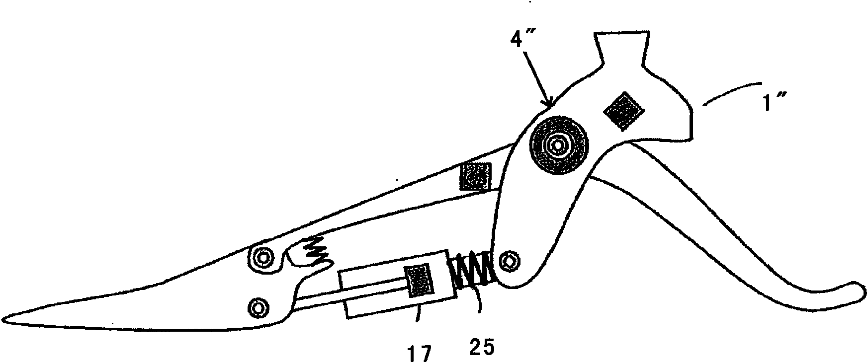
[0032] exist figure 1 In the embodiment shown in , the fixing element 1 is configured with an alignment protrusion 2 in the form of an inverted frustum of a pyramid with four slopes. The fastening part 1 forms a pot which is open at the bottom, into which the upwardly protruding web 3 of the double-arm lever 4 protrudes. The double-arm lever is rotatable about the swivel joint 5 , the swivel axis 6 of which at the same time forms the axis of the ankle joint of the artificial foot. The swivel joint 5 is provided with an angle sensor 7 . The double-arm lever 4 has a rigid downwardly projecting projection 8 .

[0033] In the downwardly open pot of the fastening part 1, the intermediate space formed by the web 3 is filled with a relatively hard elastic material 9, whereby the movement of the fastening part 1 is only slightly damped and transmitted to the contact of the double-arm lever 4 Tablet 3 movement. Thus, the protrusion 8 follows the movement of the fixture 1 , but is s...


PUM


Abstract

The invention relates to an orthopedic foot device with a connection part for the lower leg, a swivel joint (5) acting as an ankle joint (7) by means of which a foot part (10) is rotatably connected in the direction of dorsiflexion and the direction of plantar flexion to the connection part, with a damping arrangement (17) influencing the rotational movement about the swivel joint (5), with a sensor arrangement for detecting action states of the orthopedic foot part, and with a control unit connected to the sensor arrangement which controls the damping arrangement (17). The object is achieved by the fact that the sensor arrangement has an ankle-angle sensor which measures the angle between the connection part and the foot part (10), an absolute-angle sensor (20) relating to the plumb line and a moments sensor (21) for determining the torque on the ankle joint (7) or a force effecting a torque on the ankle joint (7).

Description

technical field [0001] The invention relates to an orthopedic foot part with a lower leg connecting part, a rotary joint acting as an ankle joint, by means of which a foot part of an artificial foot can be rotatably connected to the connecting part in the direction of dorsiflexion and in the direction of plantarflexion connection; having a damping device influencing the rotational movement around the rotary hinge; having a sensor device for recognizing the motion state of the artificial foot and having a control device connected to the sensor device, which controls the damping device . The invention also relates to a method for controlling such an orthopedic foot. Background technique [0002] It is known that the control of an orthopedic foot part in the form of an artificial foot or a foot orthosis has to meet a number of requirements in order for the prosthetic wearer to be able to use the artificial foot safely and achieve as natural a movement process as possible durin...

Claims


Application Information

Patent Timeline
IPC IPC(8): A61F2/66A61F2/68
CPCA61F2002/5032A61F2002/5018A61F2002/707A61F2002/745A61F2002/7645A61F2002/665A61F2002/5035A61F2002/5033A61F2/68A61F2002/5001A61F2/6607A61F2220/0033A61F2002/6621A61F2002/7625A61F2002/30359A61F2002/6642A61F2002/5007A61F2002/748A61F2/70A61F2/74A61F2/748
Inventor S·卡尔滕博恩F·吕斯S·扎林B·比朔夫T·克劳斯
Owner OTTO BOCK HEALTHCARE IP GMBH & CO KG
Why Eureka
Try Eureka