
Pressure equalizing density lock

A technology of density lock and pressure equalization, which is applied in reactors, greenhouse gas reduction, nuclear engineering, etc., can solve problems such as uneven pressure, interface oscillation, and uneven temperature distribution, so as to avoid uneven pressure distribution and uniform fluid velocity , to ensure the effect of stable layering

Inactive Publication Date: 2009-11-04
HARBIN ENG UNIV
View PDF3 Cites 0 Cited by
  • Summary
  • Abstract
  • Description
  • Claims
  • Application Information

AI Technical Summary

Problems solved by technology

The existing density lock structure has the following defects: the first, the existing density lock structure is composed of many small channels with openings at both ends, and there is no device above it for uniform fluid flow velocity field or consuming fluid turbulent kinetic energy
When there is fluid flow above the density lock, the change of velocity will lead to uneven pressure distribution among the channels in the density lock, which will lead to the formation of a large circulation between the sub-channels, thereby destroying the stability of fluid stratification; second, Due to the existence of uneven velocity distribution, changes in the velocity field will cause changes in the pressure distribution between the channels of the density-locked structure. Therefore, in the existing density-locked structure, the layered interface in each small channel of the density layered section will oscillate up and down. , which leads to uneven temperature distribution in the radial direction of the density lock, and the radial temperature difference will lead to radial heat transfer of the fluid in the small channel, thereby destroying the interface stability of the small channel
In summary, when the fluid flows above the density lock, the existing density lock structure cannot solve the problem of pressure unevenness caused by the change of the flow field, resulting in natural circulation between the density lock channels, interface oscillation and radial temperature uneven distribution problem

Method used


Image

  • Pressure equalizing density lock
  • Pressure equalizing density lock
  • Pressure equalizing density lock

Examples


Embodiment Construction

[0044] The present invention is described in more detail below in conjunction with accompanying drawing example:

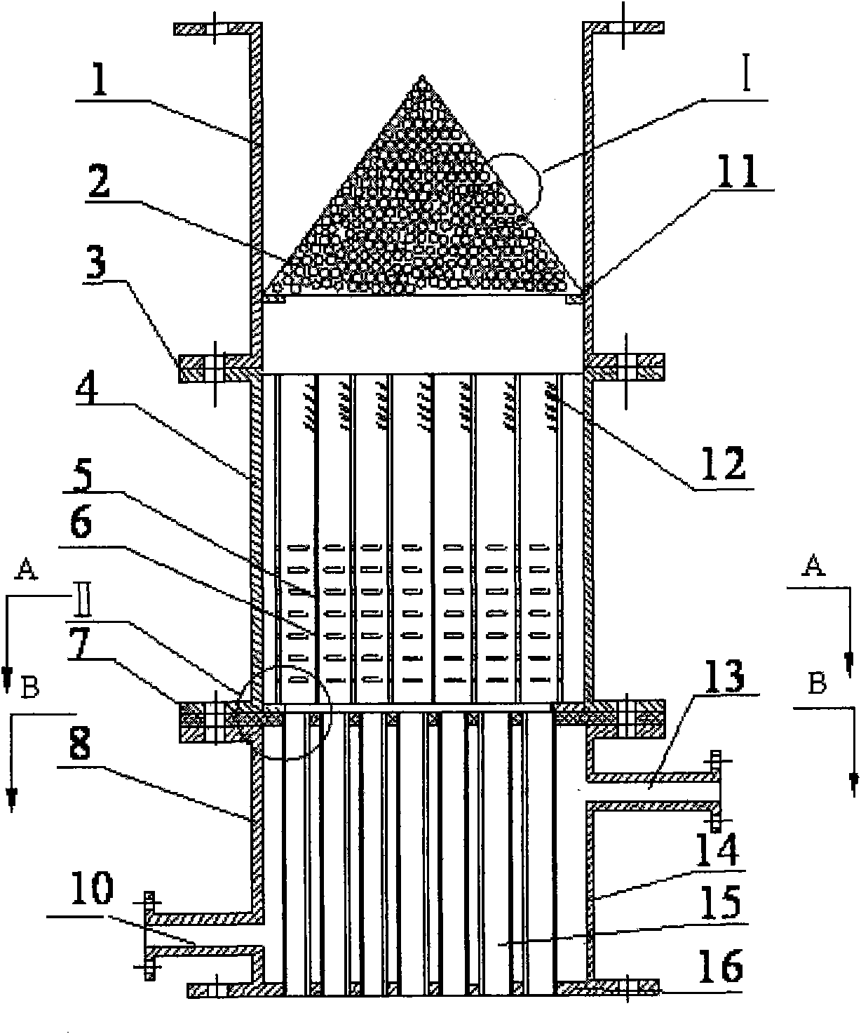
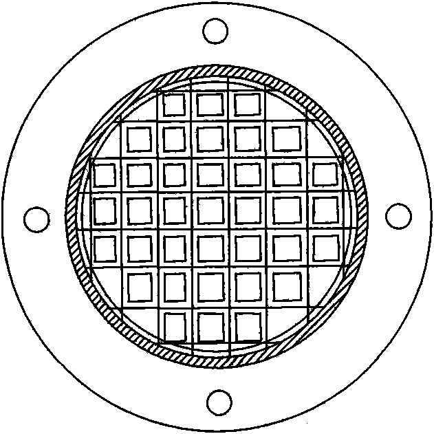
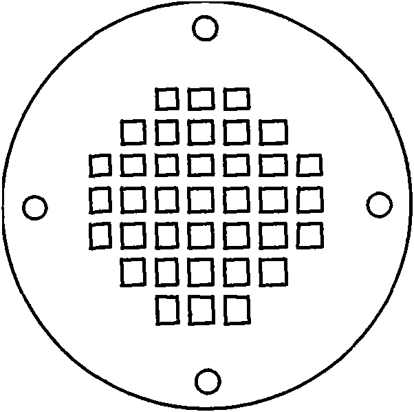
[0045] combine Figure 1-5 , the novel pressure-equalizing density lock of the present invention consists of a turbulent-flow equalizing section casing 1, a perforated conical structure 2, a supporting ring 11, a flange 3, a density-layered section casing 4, a density-layered section tube bundle 5, an inverted Thorn 12, flat hole 6, constant temperature section upper tube plate 7, constant temperature section shell 8, tube bundle gap 9, cooling water inlet 10, cooling water outlet 13, constant temperature section outer shell 14, constant temperature section tube bundle 15 and constant temperature section lower tube plate 16 compositions. The housing 1 of the turbulent flow equalizing section, the perforated conical structure 2 , the support ring 11 and the flange 3 form the turbulent flow equalizing section. The density layered section shell 4, the density layer...


PUM


Abstract

The invention provides a pressure equalizing density lock, which comprises a constant temperature section casing which is provided with a cooling water inlet and a cooling water outlet, a constant temperature section which is positioned in the constant temperature section casing and is formed by a constant temperature section tube bundle, and a density layering section which is formed by a density layering section casing and a density layering section tube bundle positioned in the density layering section casing, wherein, the density layering section is connected above the constant temperature section; a turbulent pressure equalizing section is arranged above the density layering section; the turbulent pressure equalizing section comprises a turbulent pressure equalizing section casing and a punching taper structure arranged therein; a round hole is arranged on the punching taper structure; and a burbling wing is arranged outside the round hole. The invention adopts a stable three-stage layering structure, effectively solves the problem of uneven pressure among passages caused by uneven velocity distribution at the upper part, eliminates the interfacial oscillation and interfacial wave transfer among the passages, enhances the stability of density layering in the density lock and realizes the active isolation of a primary coolant loop and an inactive residual heat removal loop during the stable operation of a reactor.

Description

(1) Technical field [0001] The invention relates to reactor passive safety system equipment, in particular to a pressure-equalizing density lock structure installed on a pipeline loop between a reactor passive waste heat discharge system and a main loop system. (2) Background technology [0002] In the 1980s, research institutions represented by Westinghouse Corporation of the United States adopted passive safety technology in the design of reactors for the first time. So far, many nuclear power plants have adopted passive safety systems to ensure the safe operation of reactors. An important approach in these passive security systems is density lock technology. The concept of "density lock" was first proposed by Babala et al. They believed that a boundary surface could be formed between two fluids with a difference in density. Under certain conditions, this boundary could effectively prevent the interaction between the two fluids. Stirring, use this principle to make an app...

Claims


Application Information

Patent Timeline
Patent Type & Authority Applications(China)
IPC IPC(8): G21C15/18
CPCY02E30/40Y02E30/30
Inventor 阎昌琪孙中宁谷海峰王升飞于沛
Owner HARBIN ENG UNIV
Learn More