Thermoelectric refrigerating device

一种热电制冷、热电器件的技术,应用在制冷机、制冷和液化、照明和加热设备等方向,能够解决热失控、故障等问题,达到有效运行的效果

Inactive Publication Date: 2012-07-18
4ENERGY LTD
View PDF7 Cites 0 Cited by
  • Summary
  • Abstract
  • Description
  • Claims
  • Application Information

AI Technical Summary

Problems solved by technology

If the gasket is out of tune such that a small area of ​​the thermoelectric device is not cooled, thermal runaway and failure are very likely

Method used


Image

  • Thermoelectric refrigerating device
  • Thermoelectric refrigerating device
  • Thermoelectric refrigerating device

Examples


Embodiment Construction

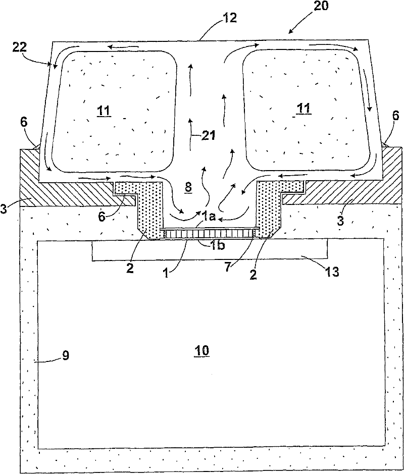
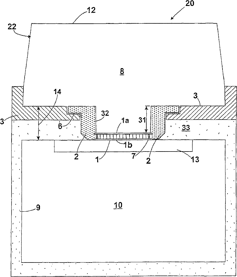
[0017] Various features related to the various aspects of the present invention can be used to enable the heat transfer liquid to safely and reliably contact the surface of the thermoelectric device, and also to facilitate the convective movement of the heat transfer liquid to the area where the heat can be dissipated to the surrounding environment without the use of Circulation pumps or cooling fans, thus eliminating components that require regular maintenance and operating power.

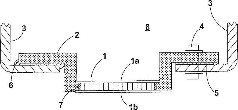
[0018] One feature relates to the method of encapsulation of thermoelectric cooling devices (also known as Peltier devices). This technique allows Peltier devices to be securely clamped or bonded to form part of a thermoelectric cooling device. This practice avoids undue mechanical stress on the Peltier device and allows the heat transfer liquid to directly contact the upper surface of the Peltier device, which usually consists of a ceramic plate. In cases where the heat transfer liquid may be in...


PUM


Abstract

A thermoelectric refrigerator apparatus (20) comprising a thermoelectric device (1) having an upper face (1a) and a lower face (1b), a sealed cavity (22) for containment of a heat transfer liquid (8) in direct thermal contact with the upper face (1a) of the thermoelectric device (1)5 the cavity (22) being configured to allow convective flow (21) of the heat transfer liquid (8) from the upper face(1a) of the thermoelectric device (1) to an upper surface (12) of the cavity comprising a heat dissipation area (12) so as to transport heat from the lower face (1b) to an external environment via theheat dissipation area (12), wherein the thermoelectric device (1) is at least partially encapsulated by an encapsulating medium (2) providing a fluid seal around a perimeter edge (7) of the thermoelectric device (1) between the upper and lower faces (1a, 1b).

Description

technical field [0001] The present invention relates to the use of thermoelectric (or Peltier) devices in thermoelectric cooling devices, and to methods of manufacturing such thermoelectric cooling devices. Background technique [0002] Thermoelectric devices are well known in the art. These devices, also known as Peltier devices, are solid-state electric heat pumps that transfer heat from one side of the device to the other when a voltage is applied. Peltier devices are mostly used for cooling, although they can also be used for heating when working in reverse. Connecting the device to a DC voltage will cause one side to get cold and the other side to get hot. The efficiency of such devices depends at least in part on how well heat is removed from the hot side. [0003] Thermoelectric devices are often assembled to form low-cost cooling devices, and their well-known disadvantages are low efficiency and the need to use fans. In engineering, the most common configuration ...

Claims


Application Information

Patent Timeline
Patent Type & Authority Patents(China)
IPC IPC(8): F25B21/02
CPCF25B21/02F25B2321/0252Y10T29/49826H10N10/13
Inventor P·A·廷代尔S·P·雷德肖
Owner 4ENERGY LTD
Why Eureka
Try Eureka